Reciprocating driver

A driving device, reciprocating technology, applied in the directions of rider driving, transportation and packaging, vehicle parts, etc., can solve the problems of easy damage of central axis parts, weak fixing and self-locking, waste of angular travel, etc., to achieve a more structural and efficient Superior riding performance and improved transmission efficiency

Inactive Publication Date: 2009-07-08
常殿林
View PDF8 Cites 0 Cited by
  • Summary
  • Abstract
  • Description
  • Claims
  • Application Information

AI Technical Summary

Problems solved by technology

[0002] The driving method of traditional bicycles is to drive the circular motion of the sprocket, but in the entire circular motion, only the range of more than 120 degrees directly in front is the best afterburning angle, and the remaining 240 degrees are the low-efficiency zone or no power zone. , thus wasting two-thirds of the angular stroke, so the transmission efficiency of the traditional bicycle can only reach 35%, and it is more difficult to travel uphill
The applicant's previous patents have solved this problem to a certain extent. After long-term tests by the applicant, this technology has disadvantages such as easy damage to the center shaft parts, weak fixation and self-locking, and difficult maintenance.

Method used


Image

  • Reciprocating driver
  • Reciprocating driver
  • Reciprocating driver

Examples


Embodiment 1

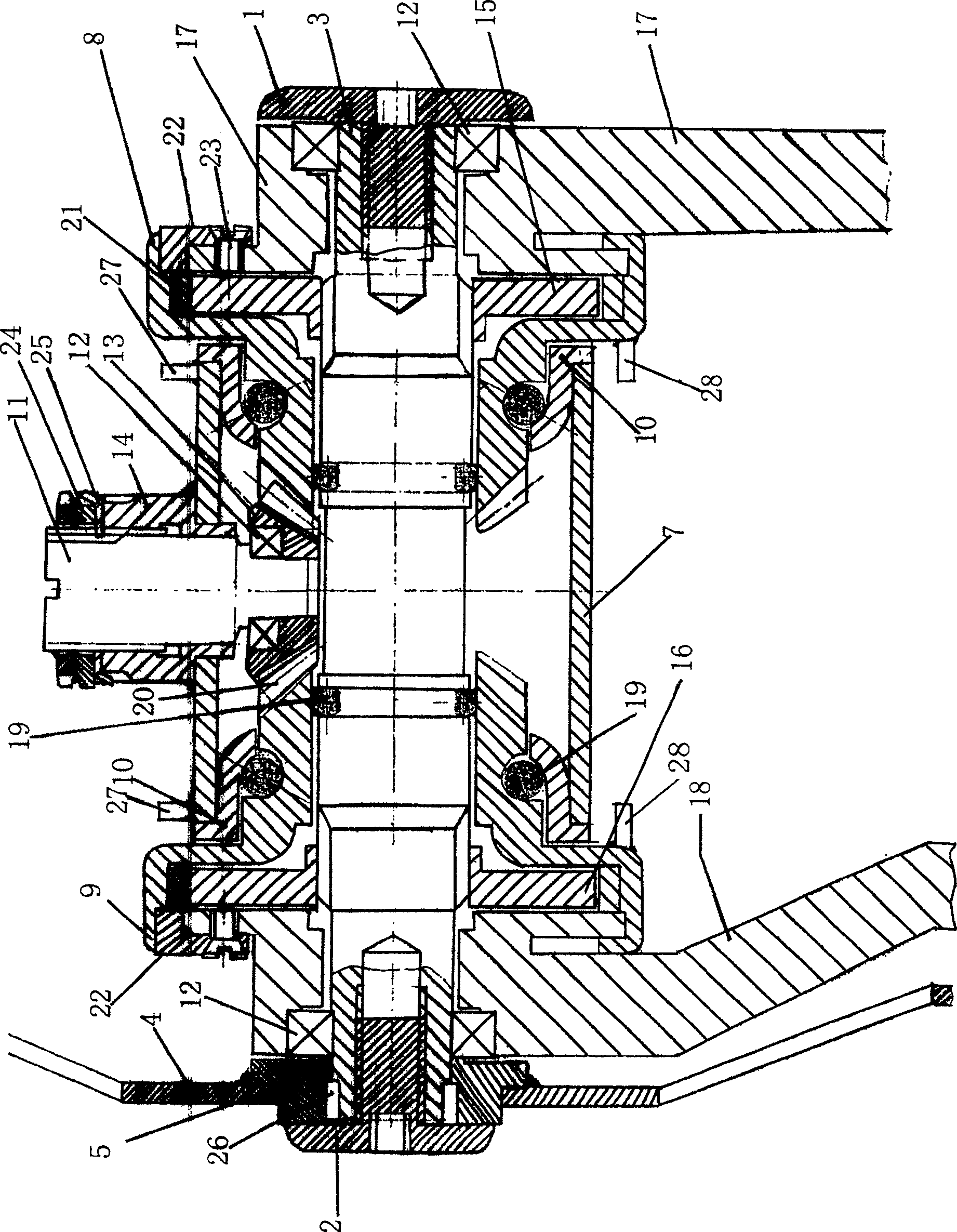
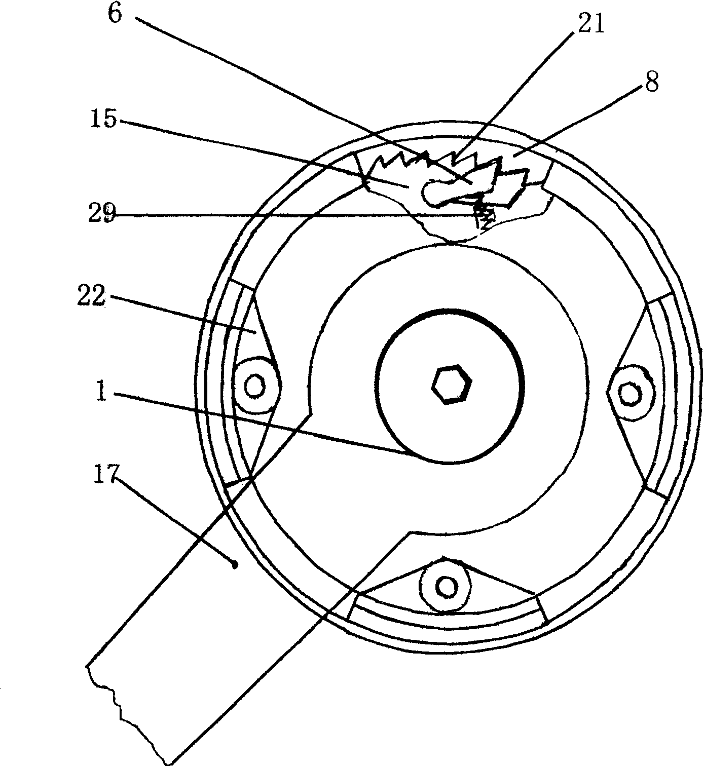
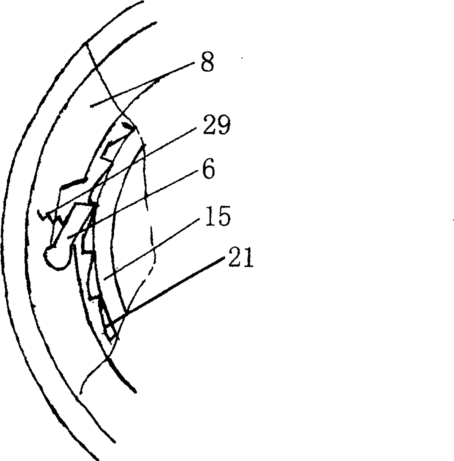
[0023] Such as figure 1 and figure 2 The reciprocating driving device shown includes left and right end covers 1 and 2, a central shaft 3, a sprocket 4, a sprocket seat 5, a pawl 6, and a central joint 7. The central shaft 3 is inside the central joint 7, and the central shaft 3 There are left and right pendulum rings 8 and 9 on the upper sleeve, and the center shaft bowl 10 is overlaid on the left and right pendulum rings 8 and 9, and a mediation shaft 11 is provided between the left and right pendulum rings 8 and 9, and the bottom of the mediation shaft 11 is provided with a bearing 12 and an intermediate joint. Wheel 13, middle connecting wheel 13 meshes with left and right pendulum rings 8 and 9 bevel teeth 20, mediation shaft 11 is located in mediation seat 14, left and right ratchets 15 and 16 on the central axis are housed in left and right pendulum rings 8 and 9, in The outsides of the left and right ratchets 15 and 16 are provided with left and right axle handles 17...

Embodiment 2

[0034] The balls in Embodiment 1 are replaced by rollers, needle rollers, bearings or oil bearings. There are three mediation shafts and three pawls. On the pendulum ring, the periphery of the left and right ratchet wheels is a ratchet, and the cross-sectional shape of the right crank is elliptical, semicircular or triangular, and the left and right pendulum rings and the left and right cranks are fixed by expansion rings.

[0035] There are 1-5 mediation shafts, which are eccentric shafts with an eccentricity of 0.1-1mm, and 1-10 ratchets.

[0036] Working principle of the present invention:

[0037] The left and right cranks installed on the central shaft are fixedly combined with the left and right swing rings respectively. Because the left and right cranks swing to drive the left and right swing rings to swing, the swing ring positioning blocks on the left and right swing rings alternately collide with the middle joint positioning blocks during driving to obtain the best ...


PUM


Abstract

The invention relates to a driving device, in particular to a reciprocating driving device which can reduce the force and increase the riding speed of a bicycle. Including the left and right end covers, the central shaft, the sprocket, the sprocket seat, the pawl, and the central joint. The left and right swing rings are covered on the central shaft, and the left and right swing rings are covered with a central shaft bowl. The mediation shaft, the bottom of the mediation shaft is provided with a bearing and a centering wheel, the centering wheel is connected to the left and right swing rings, the mediation shaft is set in the mediation seat, and the left and right ratchets are set on the center shaft in the left and right swing rings, and the left and right ratchets are on the outside There are left and right cranks which are sleeved on the central axis and fixed with the left and right swing rings. Advantages and effects of the present invention: the reciprocating express bicycle of the present invention scientifically and effectively improves the transmission efficiency of the bicycle, increases the rotational torque, and is therefore suitable for walking on slopes. Because the two cranks reciprocate up and down, and the swing angle is in the optimum afterburner range, the transmission efficiency of the bicycle is increased, the riding is brisk, and the physical strength is saved. This is a major change in the transmission structure of the bicycle.

Description

technical field [0001] The invention relates to a driving device, in particular to a reciprocating driving device which can reduce the force and increase the riding speed of a bicycle. Background technique [0002] The driving method of traditional bicycles is to drive the circular motion of the sprocket, but in the entire circular motion, only the range of more than 120 degrees directly in front is the best afterburning angle, and the remaining 240 degrees are the low-efficiency zone or no power zone. , thus wasting two-thirds of the angular stroke, so the transmission efficiency of the traditional bicycle can only reach 35%, and it is more difficult to advance when going uphill. The applicant's previous patents have solved this problem to a certain extent. Through long-term tests by the applicant, this technology has the disadvantages of easy damage to the central axis parts, weak fixing and self-locking, and difficult maintenance. Contents of the invention [0003] In ...

Claims


Application Information

Patent Timeline
Patent Type & Authority Patents(China)
IPC IPC(8): B62M1/04B62M1/24
Inventor 常殿林
Owner 常殿林
Why Eureka
Try Eureka