Electric double layer capacitor

A technology of electric double layer capacitors and batteries, which is applied in the directions of double layer capacitors, electrolytic capacitors, capacitors, etc., can solve the problems of insufficient expansion of the electric double layer area.

Inactive Publication Date: 2009-07-08
MITSUBISHI ELECTRIC CORP
View PDF3 Cites 0 Cited by
  • Summary
  • Abstract
  • Description
  • Claims
  • Application Information

AI Technical Summary

Problems solved by technology

[0011] On the other hand, since the expansion and contraction of the electrodes occur only in the stacking direction, in order to suppress the change in the amount of electrolyte in the separator, the expansion and contraction of the electrodes can be made by applying surface pressure on the main part of the large battery part It is reduced to about 10%, but when the expansion and contraction of the electrode are suppressed, since the electrolyte and the electrolyte do not enter the electrode, the expansion of the area of ​​the electric double layer is not sufficient, and the increase in the electrostatic capacity is maintained when compared with the existing activated carbon. Around 1.5 times

Method used


Image

  • Electric double layer capacitor
  • Electric double layer capacitor
  • Electric double layer capacitor

Examples


Embodiment approach 1

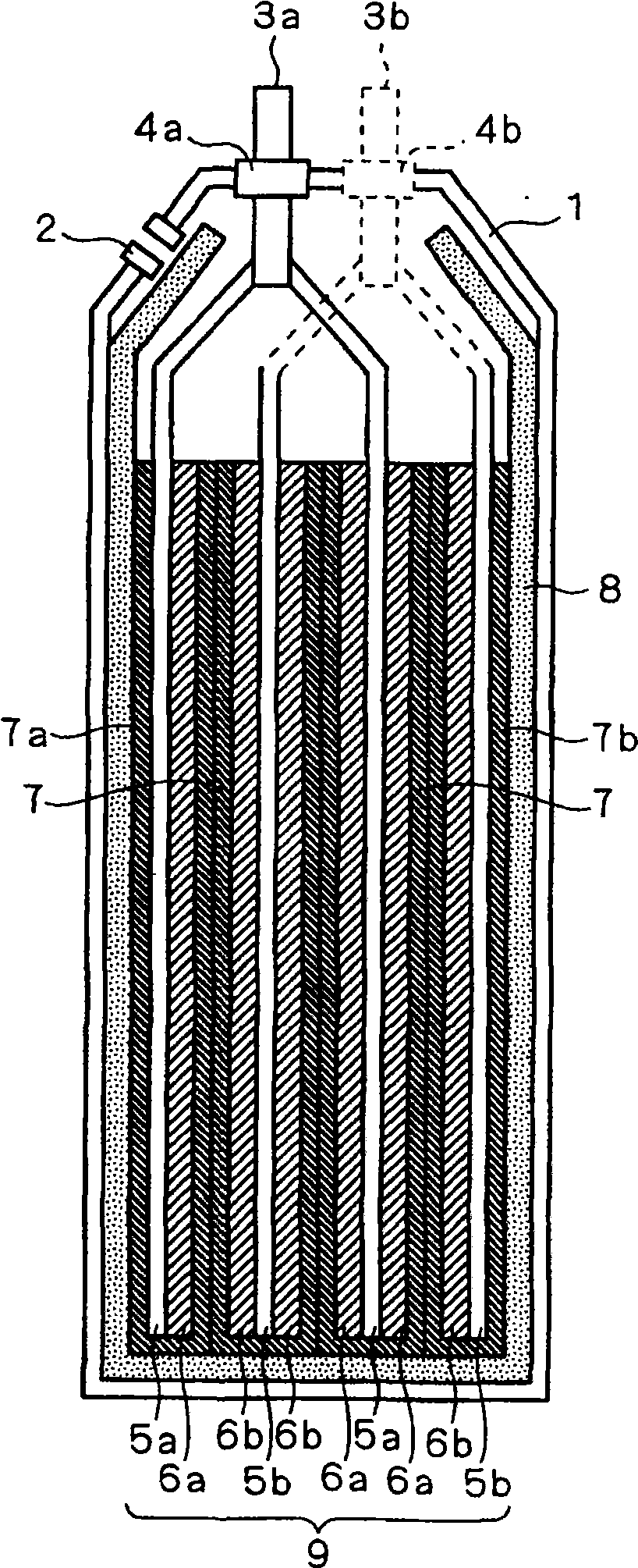
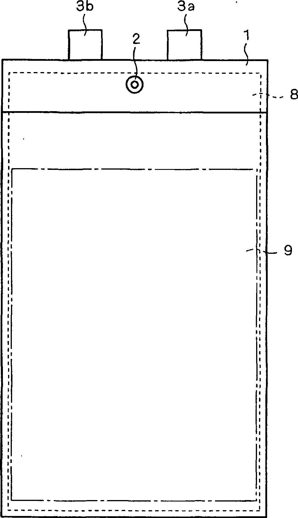
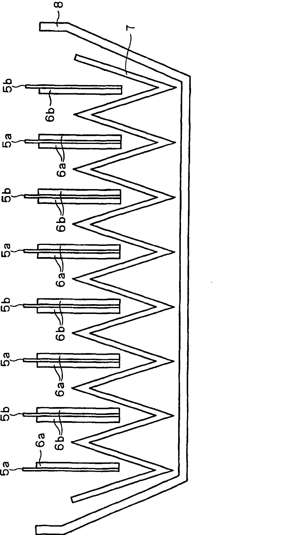
[0058] figure 1 with figure 2 Each is a cross-sectional view and a front view showing the structure of the electric double layer capacitor according to Embodiment 1 of the present invention. Reference figure 1 , 2 It can be seen that the cell portion 9 is formed by stacking multiple sets of positive electrodes 6a and negative electrodes 6b facing each other with a porous separator 7 interposed therebetween. As the positive electrode 6a and the negative electrode 6b, a layer with a thickness of several hundreds of μm can be used by bonding activated carbon with a diameter of about 10 μm and nanogate carbon with a fluorine resin such as PTFE (polytetrafluoroethylene) as an adhesive. .

[0059] The positive electrode 6a is formed on the positive electrode collector plate 5a, and the negative electrode 6b is formed on the negative electrode collector plate 5b. Aluminum foil can be used as the positive electrode current collector plate 5a, and the positive electrode 6a is formed on...

Embodiment approach 2

[0077] Figure 6 In order to show a perspective view of the structure of the electric double layer capacitor according to the second embodiment of the present invention, a part of the case 1 and the electrolyte reservoir 8 are cut away. In addition, Figure 7 To schematically show that it is cut by a virtual plane 20 Figure 6 A cross-sectional view of the cross-sectional structure of the electric double layer capacitor shown.

[0078] In the above first embodiment, an example of a laminated electric double layer capacitor is described, such as Figure 6 , 7 As shown, the present invention can also be applied to a wound type electric double layer capacitor.

[0079] The wound type electric double layer capacitor is different from the laminated type in that the battery unit 9 is formed by overlapping and winding the respective sheets of the positive electrode 6a, the separator 7 and the negative electrode 6b multiple times. The electric double layer capacitor of the second embodim...

Embodiment approach 3

[0082] Figure 8 This is a front view showing the structure of an electric double layer capacitor according to Embodiment 3 of the present invention. Such as Figure 8 As shown, the electric double layer capacitor according to the third embodiment has a case 101, an electrolyte reservoir 104 and a battery portion 105 housed in the case 101, and a positive terminal 102 and a negative terminal 103. The electrolyte reservoir 104 is composed of a plurality of electrolyte reservoirs 104a.

[0083] Picture 9 with Picture 10 Each is a cross-sectional view and a perspective view showing the structure of the electrolyte reservoir 104 and the battery section 105 in a state housed in the case 101. in Picture 10 , For the convenience of explanation, not shown in Picture 9 The separator 110 shown in. Such as Picture 9 , 10 As shown, the battery unit 105 has a structure in which a plurality of groups of positive electrodes 106 and negative electrodes 107 facing each other with a porous s...


PUM

PropertyMeasurementUnit
diameteraaaaaaaaaa
diameteraaaaaaaaaa
diameteraaaaaaaaaa

Abstract

A porous electrolytic solution reservoir which is capable of being impregnated with an electrolytic solution is provided in an exterior case so as to make contact with a separator. The average diameter of the pores in the electrolytic solution reservoir is greater than the average diameter of pores in the separator. The electrolytic solution reservoir is impregnated with a predetermined amount of electrolytic solution, so that the occupation ratio of electrolytic solution within the pores in the separator becomes 50% or more when fully charged, and the occupation ratio of electrolytic solution within the pores in the electrolytic solution reservoir becomes 100% or less when fully discharged.

Description

Technical field [0001] The present invention relates to electric double layer capacitors. Background technique [0002] Electric double layer capacitors, as disclosed in Japanese Patent Application Laid-Open No. 11-150042, are provided with polarized electrodes (positive and negative electrodes) facing each other with a separator sandwiched between them. The use of polarized electrodes in the electrolyte An electric double-layer electrostatic capacitance device formed on the surface. Electric double layer capacitors, compared with general capacitors such as aluminum capacitors, are characterized by their ability to obtain extremely large electrostatic capacitance. They are expected to be used in backup batteries of electronic equipment, storage of electricity in home appliances and copiers, and idling of automobiles. It is widely used in power supplies for starting when stopped, power supplies for hybrid vehicles, peak shaving for wind and solar power generation, and power storag...

Claims


Application Information

Patent Timeline
Patent Type & Authority Patents(China)
IPC IPC(8): H01G9/155H01G11/00H01G11/10H01G11/12H01G11/14H01G11/22H01G11/24H01G11/38H01G11/42H01G11/52H01G11/54H01G11/78
CPCY02E60/13
Inventor 光田宪朗田熊良行竹村大吾久保一树三谷彻男宮本文行増田尚
Owner MITSUBISHI ELECTRIC CORP
Why Eureka
Try Eureka