Centrifugal fan and structure of stator thereof

A centrifugal fan and stator structure technology, which is applied to non-variable volume pumps, non-displacement pumps, components of pumping devices for elastic fluids, etc. 1 Problems such as inability to operate and being easily pulled away from the motor to achieve the effect of improving the ability to resist pulling by external forces

Active Publication Date: 2009-07-15
DELTA ELECTRONICS INC
View PDF5 Cites 0 Cited by
  • Summary
  • Abstract
  • Description
  • Claims
  • Application Information

AI Technical Summary

Problems solved by technology

However, neither the cable tie L nor the wire 13 is fixed on the base 12, and will still move in the opening 121, and when the wire 13 is pulled by an external force, the wire 13 is easily pulled away from the motor because it is not clamped and fixed, thereby causing Centrifugal fan 1 not working
In addition, since the wire 13 cannot cover the opening 121, foreign matter, dust or moisture may enter the base 12 through the opening 121.

Method used


Image

  • Centrifugal fan and structure of stator thereof
  • Centrifugal fan and structure of stator thereof
  • Centrifugal fan and structure of stator thereof

Examples


Embodiment Construction

[0019] A centrifugal fan and its stator structure and base structure according to preferred embodiments of the present invention will be described below with reference to the accompanying drawings, wherein the same elements will be described with the same reference numerals.

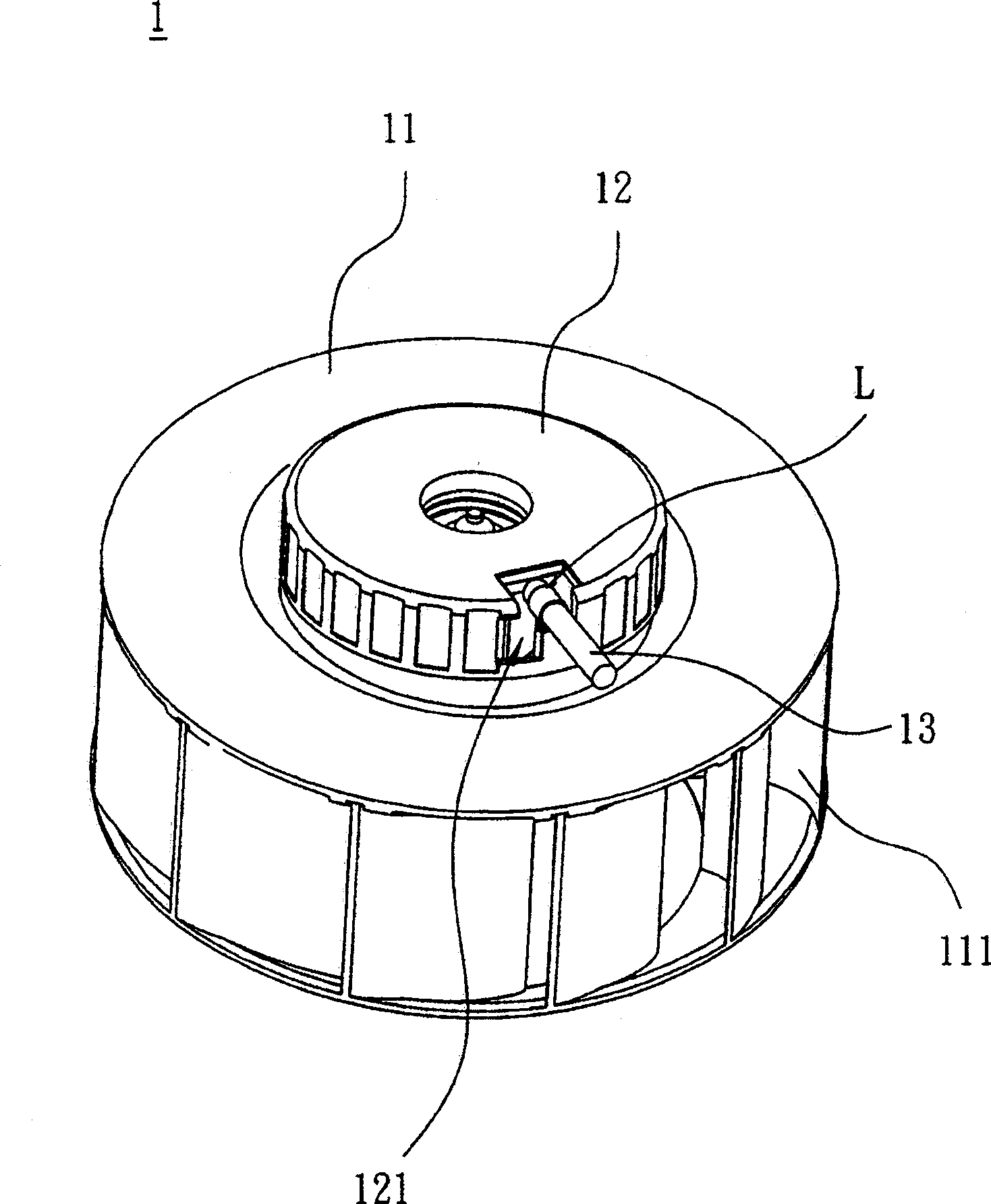
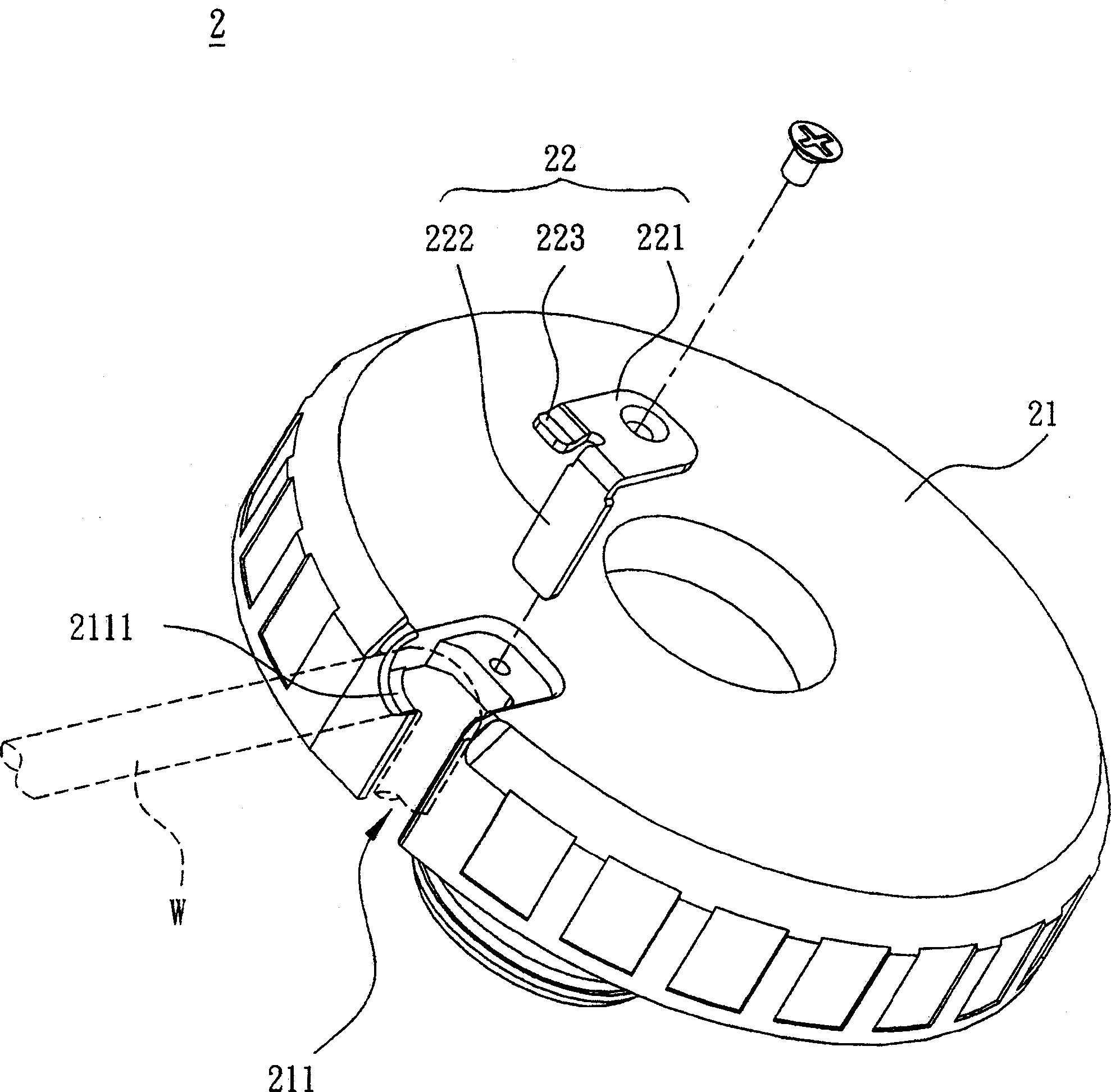
[0020] refer to figure 2 , a centrifugal fan seat structure 2 according to a preferred embodiment of the present invention can fix a wire W, and the seat structure 2 includes a body 21 and a fixing member 22 . A groove 211 is formed on the periphery of the body 21 , and the wire W can easily pass through the groove 211 to be placed in a positioning portion 2111 of the groove 211 .

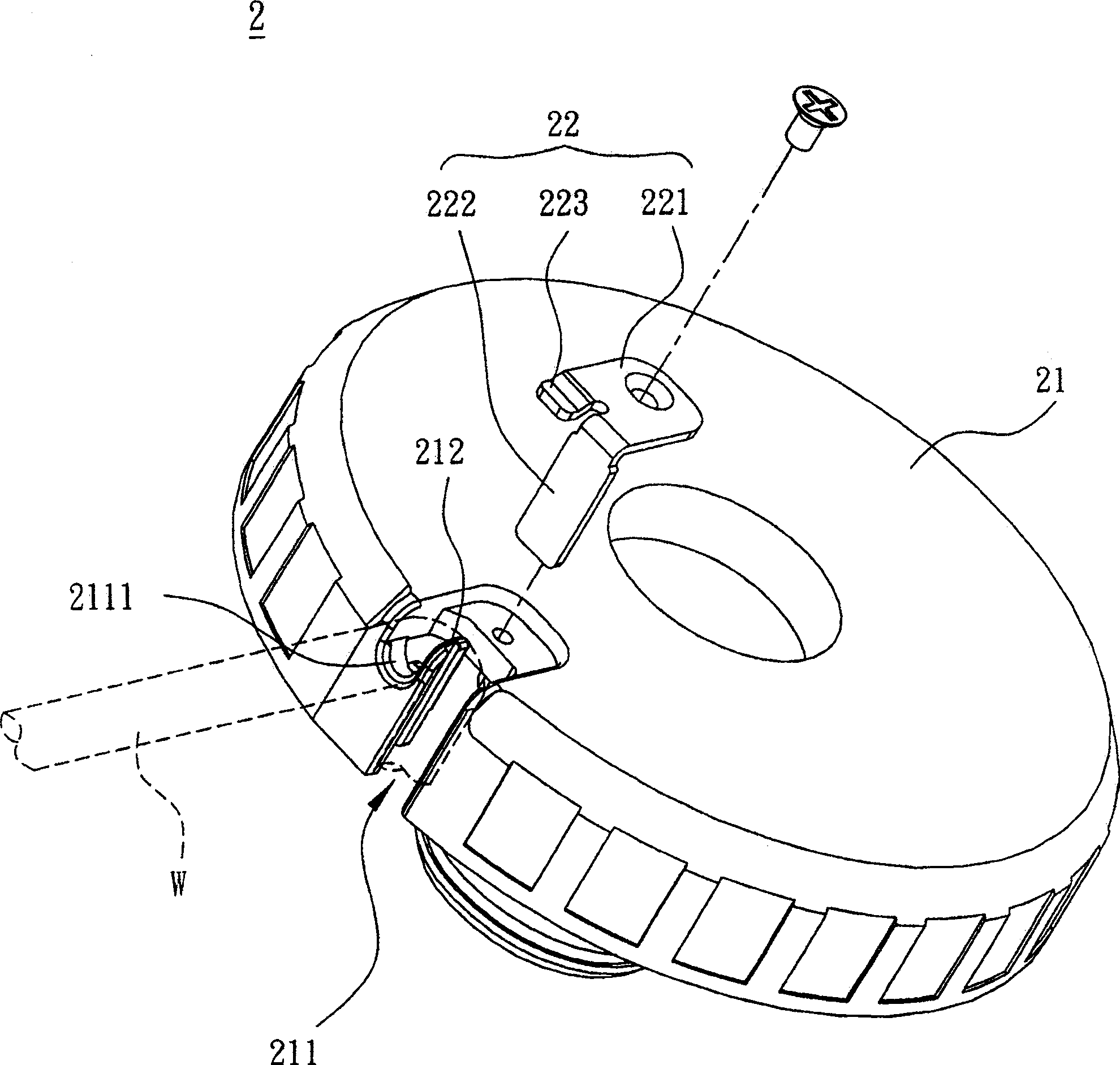
[0021] refer to image 3 In order to align and fix the wire W on the positioning part 2111 more accurately, the body 21 also has a stopper part 212, which protrudes from the groove 211 and adjoins the positioning part 2111, and is used to limit the positioning of the wire W. Section 2111. The material of the body 21 in th...


PUM


Abstract

A seat structure of a centrifugal fan includes a body and a fixing piece. The periphery of the body has at least one groove, the fixing piece has a first end and a second end, the first end is connected with the body, and the second end corresponds to the shielding groove.

Description

technical field [0001] The invention relates to a fan and its stator structure and base structure, in particular to a centrifugal fan and its stator structure and base structure. Background technique [0002] Due to the advancement of modern technology, for various multimedia equipment and large or small electronic equipment, due to the increasing performance requirements, the number of electronic components used is increasing, and the demand for heat dissipation is also increasing. This is mainly due to heat dissipation. The quality of the battery directly affects the life of electronic equipment. [0003] It is a common structural setting to use a fan as a cooling device, such as figure 1 As shown, a known centrifugal fan 1 includes an impeller 11, a base 12 and a motor (not shown in the figure), which are arranged in the base 12. The impeller 11 has a plurality of fan blades 111 and is connected to the motor. The motor is electrically connected to the outside through an...

Claims


Application Information

Patent Timeline
Patent Type & Authority Patents(China)
IPC IPC(8): F04D17/08F04D29/28F04D29/00
Inventor 林昱志陈弘琪黄文喜
Owner DELTA ELECTRONICS INC
Why Eureka
Try Eureka