Eureka AIR delivers breakthrough ideas for toughest innovation challenges, trusted by R&D personnel around the world.

Double passage differential anti-jamming current amplification circuit

A technology of current amplification and differential amplifier, which is applied in the direction of differential amplifier, DC-coupled DC amplifier, and the use of electric/magnetic devices to transmit sensing components, etc., which can solve the problems of high measurement accuracy, reduced measurement signal-to-noise ratio, and inability to completely shield interference signals and other problems to achieve the effect of suppressing common-mode interference signals and improving the measurement signal-to-noise ratio

Inactive Publication Date: 2009-08-19
UNIV OF SCI & TECH OF CHINA
View PDF4 Cites 0 Cited by
  • Summary
  • Abstract
  • Description
  • Claims
  • Application Information

AI Technical Summary

Problems solved by technology

These technologies have a common disadvantage: better shielding devices must be used to prevent various external interference signals (such as 50HZ power supply line interference, mobile phone, radio signals, etc.) The current measurement signal is amplified by the measurement circuit together with it, resulting in a decrease in the measurement signal-to-noise ratio
This makes it difficult to obtain high measurement accuracy for many field measurements that are inconvenient to use shielding devices
Even for measurements where shielding is used, it is often not possible to completely shield interfering signals, which also does not improve the signal-to-noise ratio of the measurement circuit to its highest possible value
In addition, other non-electrical disturbances such as thermal drift and vibration noise will also have a significant impact on weak current measurements

Method used


Image

  • Double passage differential anti-jamming current amplification circuit
  • Double passage differential anti-jamming current amplification circuit
  • Double passage differential anti-jamming current amplification circuit

Examples


Embodiment 1

[0033] Embodiment 1: Dual-reference input type dual-channel differential anti-interference current amplifier circuit of the present invention

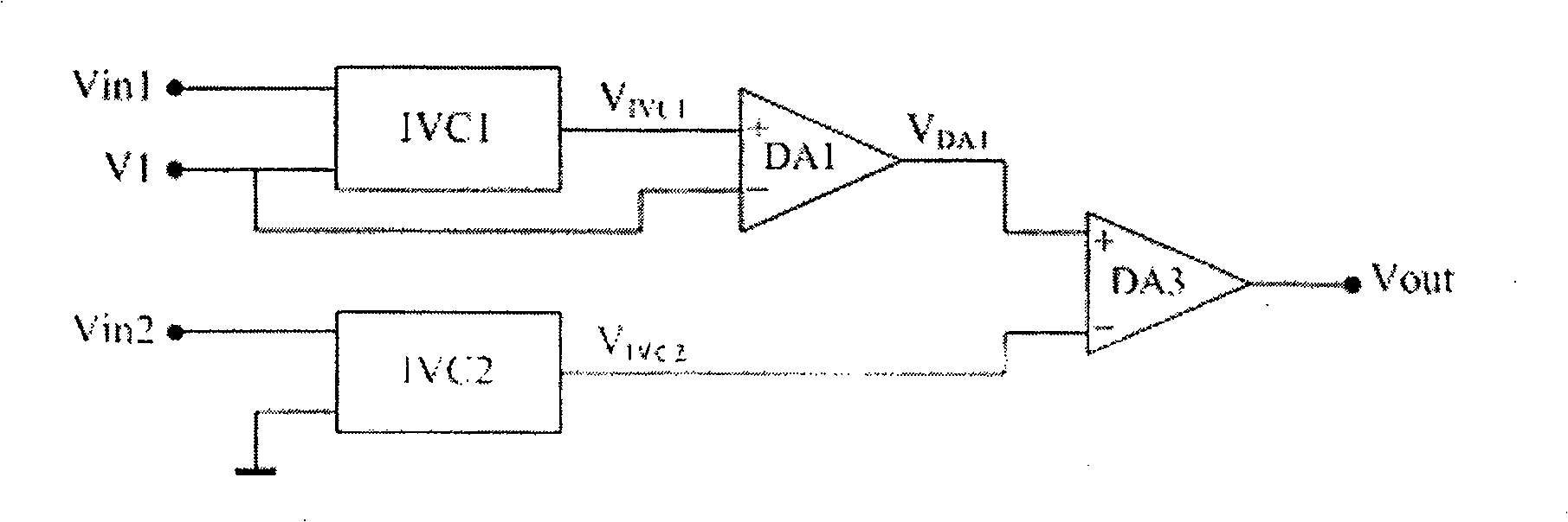
[0034] see figure 1 , the input terminal Vin1 of the first current-voltage converter IVC1 and the input terminal Vin2 of the second current-voltage converter IVC2 respectively constitute the first input terminal Vin1 and the second input terminal Vin2 of the dual-channel differential anti-interference current amplifying circuit of the present invention , the reference voltage terminal V1 of IVC1 and the reference voltage terminal V2 of IVC2 respectively constitute the first reference input terminal V1 and the second reference input terminal V2 of the dual-channel differential anti-interference current amplifier circuit of the present invention, the output V of IVC1 IVC1 and the output of IVC2 V IVC2 Connect the positive input terminals of the first differential amplifier DA1 and the second differential amplifier DA2 respectively, V1 ...

Embodiment 2

[0038] Embodiment 2: Single reference input type dual-channel differential anti-interference current amplifier circuit of the present invention

[0039] The output V of the first current-voltage converter IVC1 in the above-mentioned embodiment 1 DA1 and the output V of the second current-voltage converter IVC2 DA2 It depends on the first reference input V1 and the second reference input V2 of the dual-channel differential anti-interference current amplifying circuit of the present invention, so the first differential amplifier DA1 and the second differential amplifier DA2 are used to convert V1 and V2 from V DA1 and V DA2 deducted, so that the output signal Vout of the secondary differential amplifier DA3 does not appear to be the same as the measured current I X Nothing to do with V1 and V2. Therefore, if V1 or V2 is grounded (zero potential), its corresponding first differential amplifier DA1 or second differential amplifier DA2 can be removed to form a single-reference i...

Embodiment 3

[0041] Embodiment 3: The current-voltage converter in the dual-channel differential anti-interference current amplifying circuit of the present invention

[0042] The current-voltage converters IVC1 and IVC2 in the above-mentioned embodiment 1-2 must meet the following two conditions to make the present invention work normally: the first, the measured current I X Converted into a voltage signal V(I X ), the second, V(-I X )=-V(I X ). Current-voltage converters satisfying these two conditions can be used as IVC1 and IVC2 of the present invention, such as transimpedance amplifiers, integrators, switch integrators, and the like.


PUM


Abstract

The invention relates to a differential anti-jamming current amplifying circuit with two channels, wherein a first and a second input ends of an electric current-voltage convertor are used as a first and a second input ends of the invention, and reference voltage ends of the first and the second input ends are used as a first and a second reference input ends, the output ends of the first and the second electric current-voltage convertors are respectively connected with positive input ends of a first and a second differential amplifiers, the first and the second reference input ends are respectively connected with negative input ends of the first and the second differential amplifiers, the output ends of the first and the second differential amplifiers are respectively connected with a positive-negative input end or a negative-positive input end of a secondary differential amplifier, and the output end of the secondary differential amplifier is the output end of the invention. The invention successfully measures weak signal of pien grade under the condition without a screen, measuring signal-to-noise ratio can be further improved under the condition with the screen, and non-electric common mode interference signal of vibration, thermal drift and the like can be inhibited.

Description

technical field [0001] The invention relates to a current amplifying circuit, in particular to a dual-channel differential anti-interference current amplifying circuit suitable for weak current measurement. Background technique [0002] Many important electrical (such as tunneling current of scanning tunneling microscope, electrocardiogram, brain wave, etc.) or non-electrical (light, sound, pressure and PH value, etc.) signal measurements are finally obtained by converting them into current measurements by circuits or sensors High measurement accuracy. Therefore, the measurement of current, especially the accurate measurement of weak current is becoming more and more critical. Existing weak current measurement technologies mainly include: transimpedance amplifier circuit, integration circuit, switched integration circuit, double channel cross-correlation amplification technology, etc. These technologies have a common disadvantage: better shielding devices must be used to p...

Claims


Application Information

Patent Timeline
Patent Type & Authority Patents(China)
IPC IPC(8): G01D5/14H03F3/45
Inventor 侯玉斌陆轻铀
Owner UNIV OF SCI & TECH OF CHINA
Why Eureka
Eureka Blog
Learn More