Micro-channel fast neutron time-of-flight detector

A time-of-flight and fast neutron technology, which is applied in the field of micro-channel fast neutron time-of-flight detectors, can solve the problem that signals cannot be measured, and achieve the effects of large sensitive thickness, high measurement signal-to-noise ratio, and high detection efficiency

Active Publication Date: 2021-01-26
LASER FUSION RES CENT CHINA ACAD OF ENG PHYSICS
View PDF18 Cites 0 Cited by
  • Summary
  • Abstract
  • Description
  • Claims
  • Application Information

AI Technical Summary

Problems solved by technology

[0005] In view of this, the present invention provides a microchannel fast neutron time-of-flight detector to solve the problem in the prior art that when the neutron source to be tested produces two kinds of neutrons with different energies and intensities, the latter signal cannot be detected. Measurement technical issues

Method used


Image

  • Micro-channel fast neutron time-of-flight detector
  • Micro-channel fast neutron time-of-flight detector
  • Micro-channel fast neutron time-of-flight detector

Examples


Embodiment Construction

[0023] The present invention will be further described below in conjunction with embodiment and accompanying drawing.

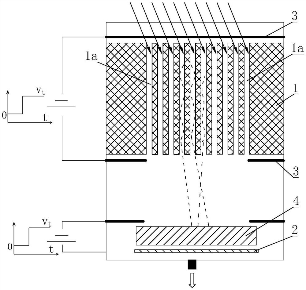
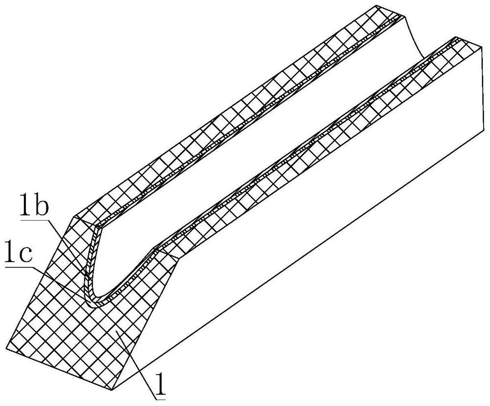
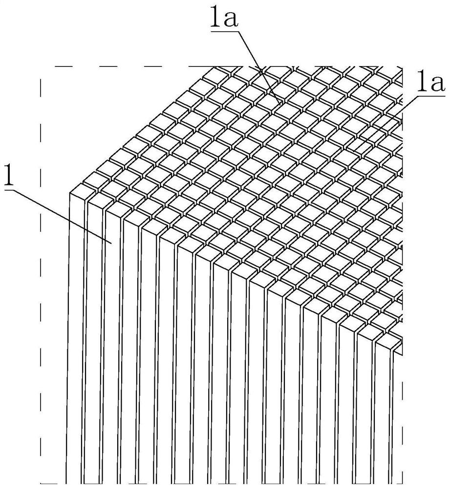
[0024] Such as figure 1 and 2 As shown, a microchannel type fast neutron time-of-flight detector, the core components involved in the detector are: neutron absorber 1, microchannel plate 4 and electron collector 2, the microchannel plate 4 is located in the neutron absorber Between the neutron absorber 1 and the electron collector 2, wherein the neutron absorber 1 is also a microchannel structure, which is made of polyethylene. There are several channels 1a running through the thickness direction of the neutron absorber 1, and the channel 1a A conductive layer 1c and a secondary electron emission layer 1b are sequentially plated on the inner wall of the neutron absorber 1. An electrode 3 is respectively provided on the sides of the corresponding two ends of the channel 1a, and a voltage is loaded between the two electrodes 3 for An electric field is formed ...


PUM


Abstract

The invention discloses a micro-channel fast neutron flight time detector which comprises a neutron absorber and an electron collector arranged at one side of the neutron absorber, a plurality of channels are distributed in the neutron absorber in an array mode, secondary electron emission layers are arranged on the inner walls of the channels, and each channel penetrates through the thickness direction of the neutron absorber. The neutron absorber is provided with electrodes on the side surfaces corresponding to the two ends of the channel respectively, a time gating pulse high voltage is loaded between the two electrodes and used for forming an electric field in the channel, and the direction of the electric field faces the electron collector. The detector has the advantages that signalsof the neutron time-of-flight spectrum can be gated in the time domain, and the measurement signal-to-noise ratio of weak signals under strong interference is higher.

Description

technical field [0001] The invention belongs to the technical field of neutron energy spectrum measurement, in particular to a microchannel fast neutron time-of-flight detector. Background technique [0002] The time-of-flight method is a common method for measuring neutron energy spectrum. This method obtains the flight speed of neutrons by measuring the flight distance L and flight time t of neutrons, that is: v=L / t, and then uses the formula " E=1 / 2mv 2 "Deduce the energy E of the neutron. [0003] In the prior art, the commonly used device for measuring neutron energy by using the time-of-flight method is a scintillation detector. The scintillation detector is composed of an organic scintillator and a photomultiplier tube. The scintillator produces fluorescence, and part of the fluorescence is collected by the photomultiplier tube to form an electrical signal, and then the neutron flight distance L and flight time t can be obtained, thereby obtaining the neutron energy...

Claims


Application Information

Patent Timeline
Patent Type & Authority Applications(China)
IPC IPC(8): G01T3/00
CPCG01T3/006
Inventor 唐琦宋仔峰刘品阳易涛肖云青刘忠杰
Owner LASER FUSION RES CENT CHINA ACAD OF ENG PHYSICS
Why Eureka
Try Eureka