Structure of jointing and releasing connecting piece

A release piece and connection technology, which is applied to the parts of the connection device, the connection, the coupling device, etc., can solve the problems of the base 104 being easily deformed and the locking piece 103 being difficult to bend, etc.

Inactive Publication Date: 2009-09-02
YAZAKI CORP
View PDF9 Cites 0 Cited by
  • Summary
  • Abstract
  • Description
  • Claims
  • Application Information

AI Technical Summary

Problems solved by technology

Especially when the protrusion length of the lock lever 103 is short, because the bending of such a short lock piece 103 is difficult, it is necessary to bend the lock lever 103 forcefully, and the stress concentration is greater on the base 104, making the base 104 more easily deformed

Method used


Image

  • Structure of jointing and releasing connecting piece
  • Structure of jointing and releasing connecting piece
  • Structure of jointing and releasing connecting piece

Examples


Embodiment Construction

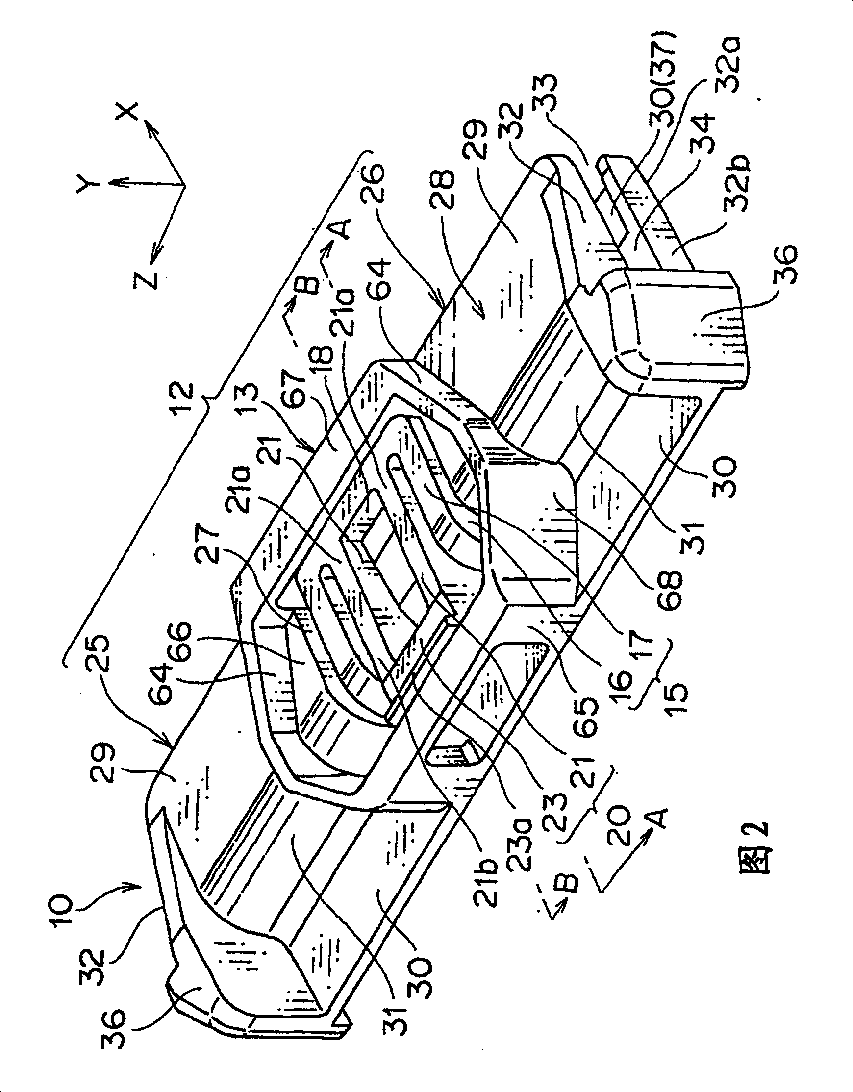
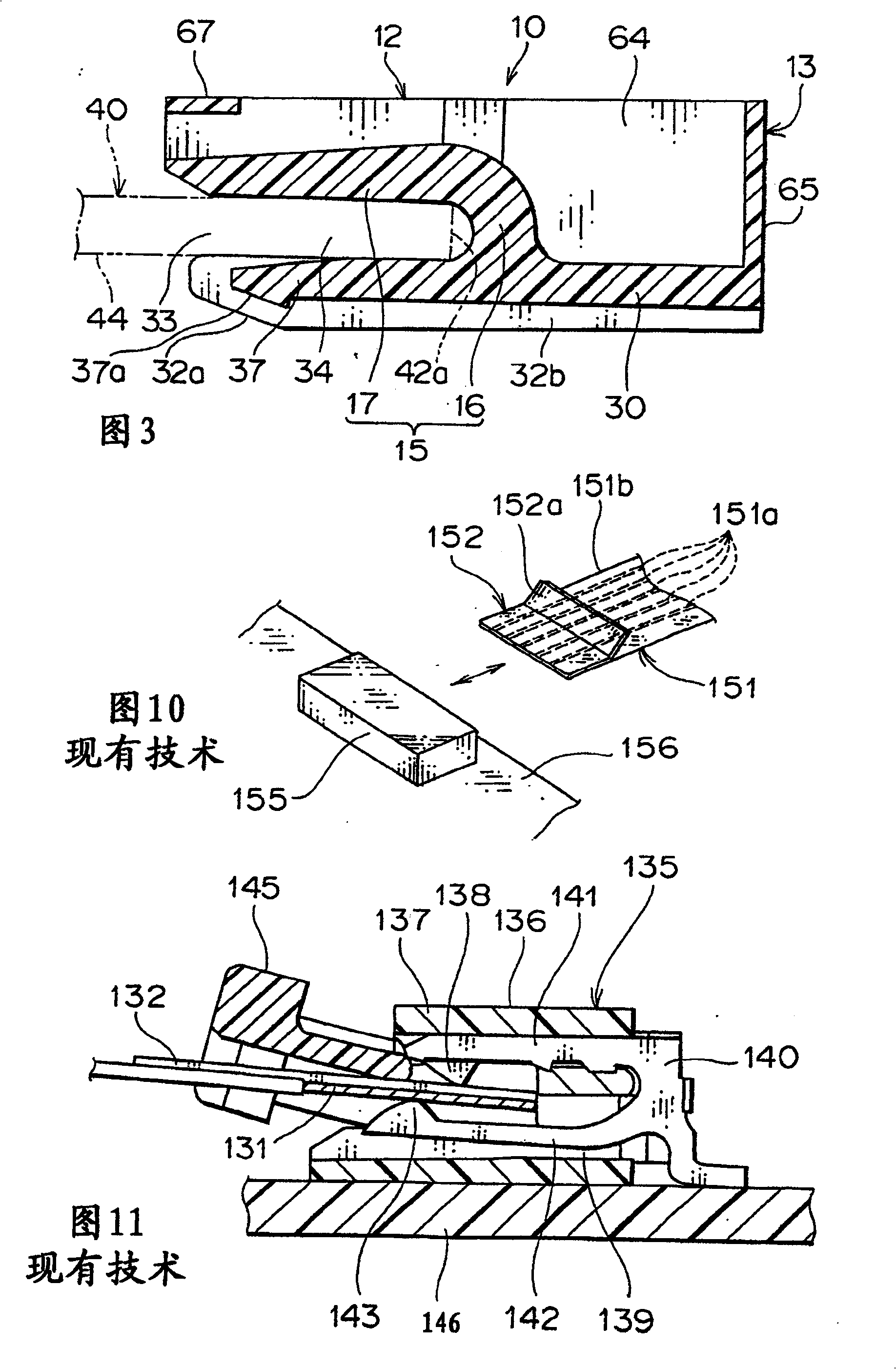
[0064] now refer to Figures 1 to 5 One embodiment of the structure of the connecting shield joint according to the present invention will be described.

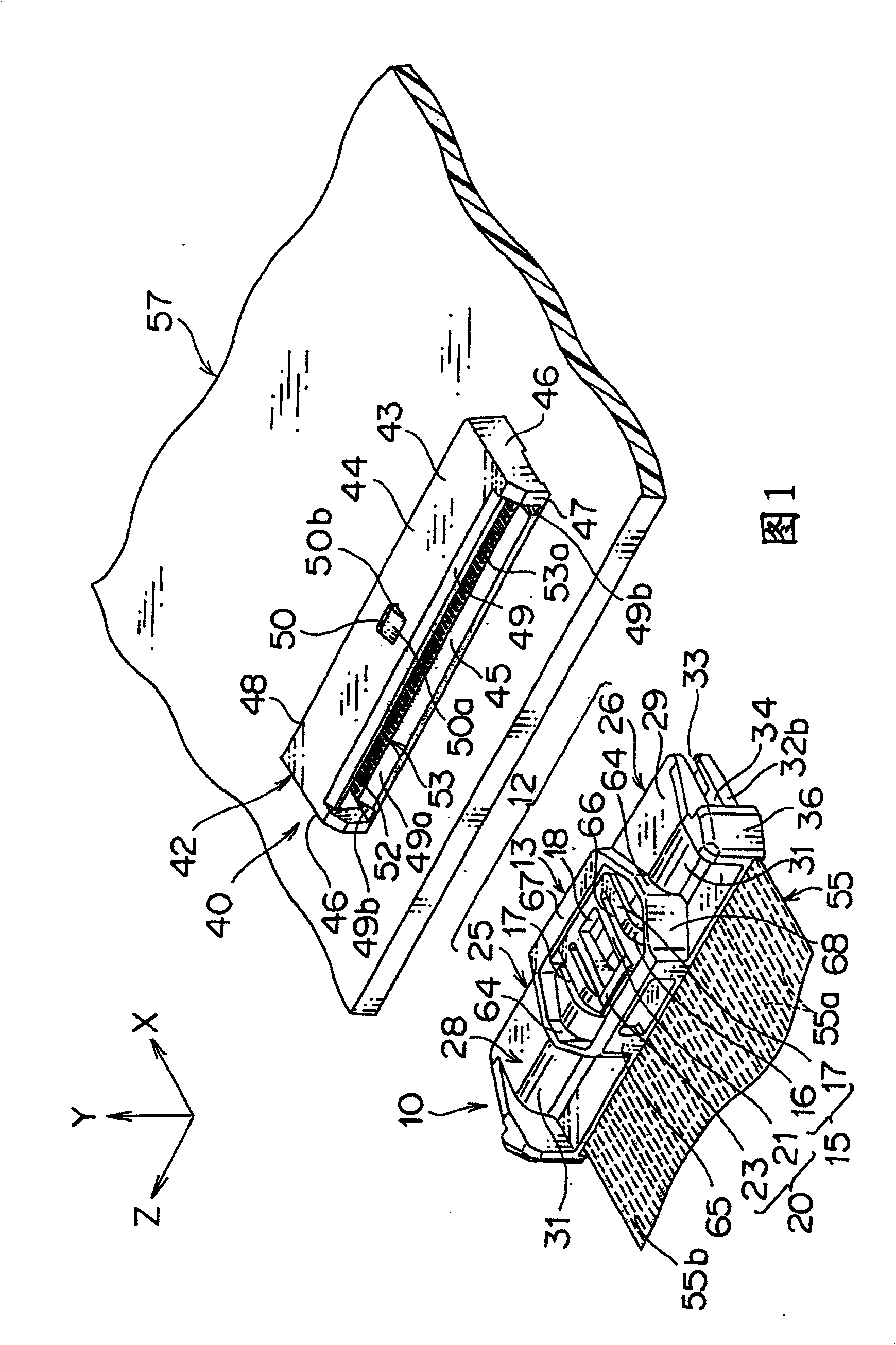
[0065] figure 1 Indicates a male connector (second connector) 10, a flexible flat cable (FFC) 55 connected as a flat wire body to the male connector 10, and a female connector (first connector) 40 mounted directly on a printed wiring board ( PCB) 57, as a circuit board.

[0066] The FFC55 is an insulated cable for transmitting a control signal or the like between devices mounted on an automobile, which includes a plurality of conductor bodies 55a arranged in parallel. A covering portion 55b for covering the wire body 55a is an insulating layer made of synthetic resin including polyvinyl chloride resin, polyethylene resin and the like. Several lead bodies correspond to several terminals 53 accommodated in the female fitting 40 .

[0067] In addition, a flexible printed wiring board (FPC, not shown) can also be used as th...


PUM


Abstract

A leg portion is provided at a second connector so that a gap is created between a flat circuit body and a circuit board. The leg portion also serves as a positioning projection, and a locking hole for being engaged with the positioning projection is provided at the flat circuit body. A guiding groove for receiving the leg portion is formed at a first connector. A guiding part for receiving the first connector in a sliding manner is formed at an end of an opening of the first connector, and an inclined part for sliding the guiding part there along is formed at an end of an engaging part of the second connector.

Description

technical field [0001] The present invention relates to a structure for engaging and releasing a connector for transmitting a control signal of an electric device. Background technique [0002] Some examples of connectors having a flat wire body are disclosed in Japanese Utility Model Application Laid-Open No. Hei 1-111478 and Japanese Patent Application Laid-Open No. Hei 9-63718. An example of a joint having a locking lever for maintaining the engaged state of the joint is disclosed in Japanese Patent Application Laid-Open No. 2000-164295. [0003] Such as Figure 10 As shown, according to the invention disclosed in Japanese Utility Model Application Laid-Open No. Hei 1-111478, a flat electric wire body 151 can be reliably inserted into a directly mounted connector 155 which is directly mounted on a circuit board 156 . [0004] The flat wire body 151 has a plurality of wire conductors 151a arranged on a flexible insulating layer 151b made of synthetic resin. The flat ele...

Claims


Application Information

Patent Timeline
Patent Type & Authority Patents(China)
IPC IPC(8): H01R13/629H01R13/631H01R13/627H01R13/639
CPCH01R13/6272H01R12/79H01R12/88
Inventor 植田裕久松村薰
Owner YAZAKI CORP
Why Eureka
Try Eureka