Locking device

A technology of locking device and locking mechanism, which is applied in the direction of transportation and packaging, special position of the vehicle, vehicle seat, etc., and can solve the problems that the detachable seat cannot fix the main body of the vehicle, and the striker does not engage with the hook rod, etc.

Inactive Publication Date: 2013-10-30
MITSUI KINZOKU ACT
View PDF6 Cites 6 Cited by
  • Summary
  • Abstract
  • Description
  • Claims
  • Application Information

AI Technical Summary

Problems solved by technology

However, in the case where the lock mechanism receiver is fixed to the support, if the relative position between the lock mechanism receiver and the striker deviates from the ideal position, there is a risk that the striker will not engage the hook bar, so that the detachable The seat cannot be fixed to the vehicle body

Method used


Image

  • Locking device
  • Locking device
  • Locking device

Examples


no. 1 example

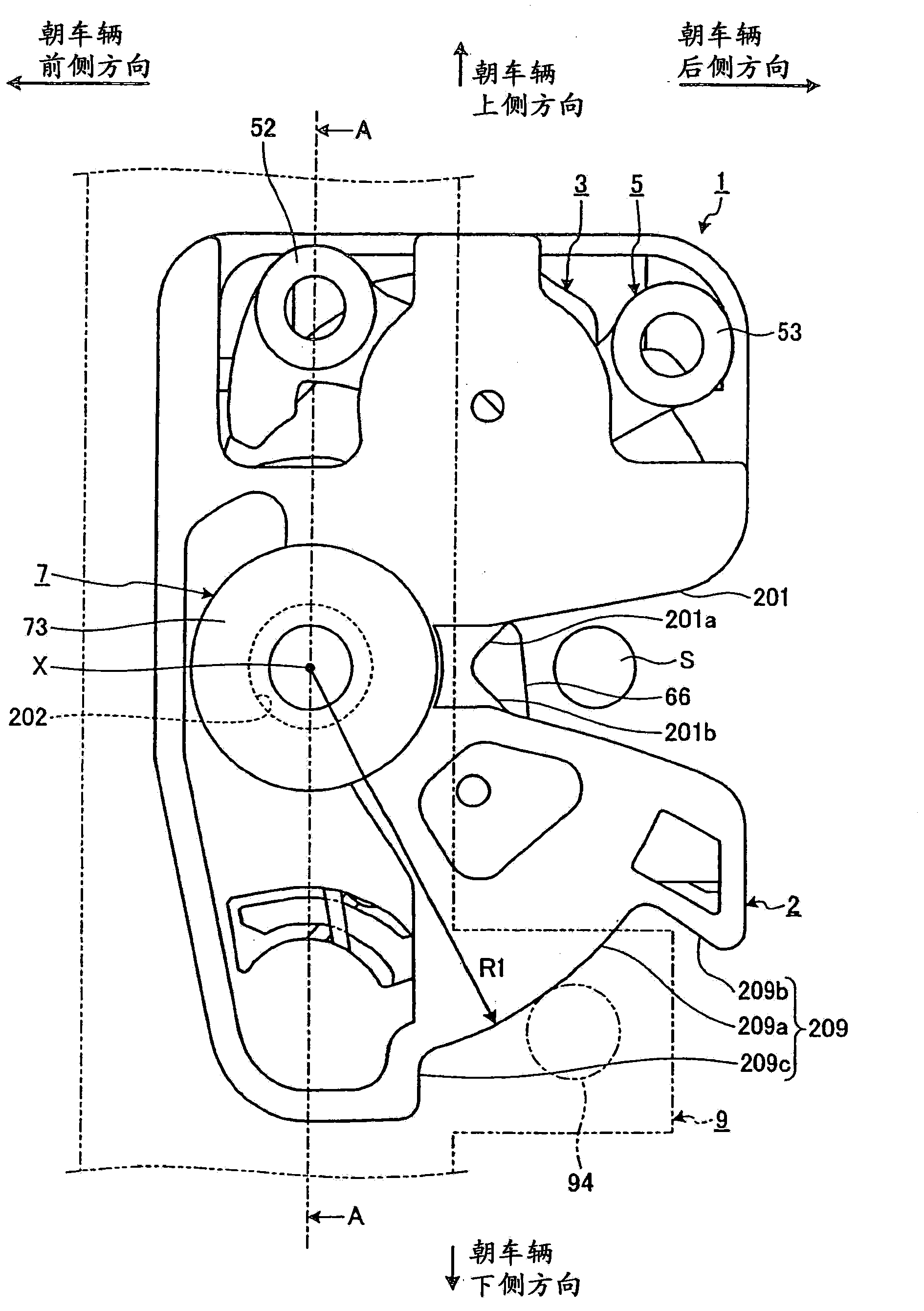
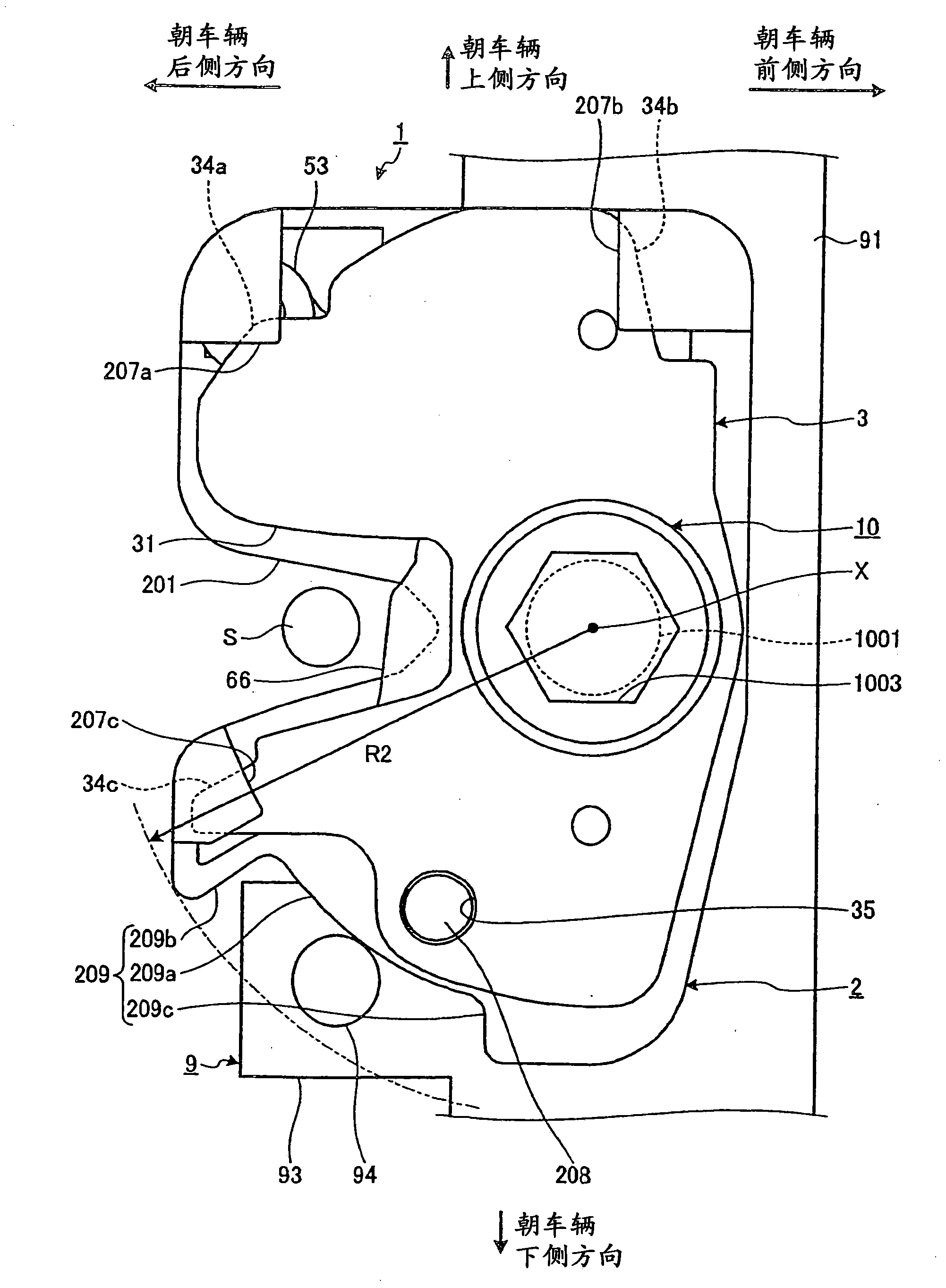
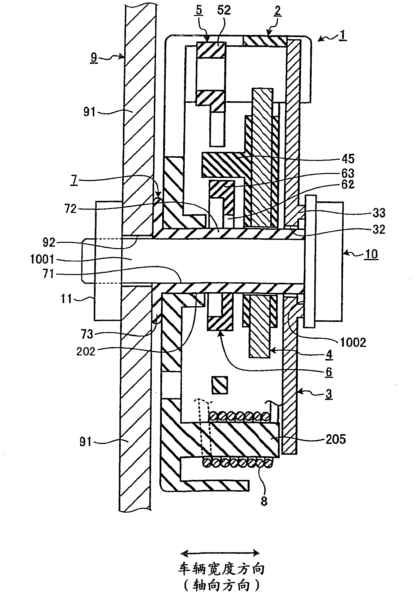
[0031] figure 1 is a plan view showing a schematic structure of the locking device in the first embodiment according to the present invention. figure 2 show figure 1 on the opposite side of the locking mechanism in the image 3 is shown along the line A-A figure 1 cross-sectional view. Figure 4 is a view showing the internal structure of the locking device. Figure 5 is an exploded oblique perspective view showing a structural example of the hook shaft insertion hole formed in the main body portion of the lock device.

[0032] The function of the locking device in the first embodiment is to fix the detachable seat (movable seat) to the vehicle main body (ie, vehicle body). Such a locking device 1 is provided in a detachable seat, connected to a frame 9 (ie, a support) of a backrest part (back support part) of the detachable seat. Such as Figures 1 to 4 As shown, the locking device 1 includes a locking mechanism receiver and a locking mechanism. The locking mechanism...

no. 2 example

[0067] Figure 12 is a plan view showing a schematic structure of a locking device according to a second embodiment of the present invention. Figure 13 yes Figure 12 A cross-sectional view of the , which is at Figure 12 taken along the line B-B in the direction of the arrow.

[0068] In the locking device of the first embodiment, the rotation range of (the main body part 2 of) the locking device 1 is limited by the rotation restricting part 209 of the main body part 2 and the rotation restricting protrusion 94 of the frame 9 . Compared with the first embodiment, in the second embodiment, the rotation range of the locking device 1 is determined by the rotation limiting protrusion 2010 provided on the main body part 2 and the rotation limiting elongated hole (slot hole) 95 provided in the frame 9 restrictions such as Figure 12 with 13 shown. Viewed from the axial direction of the hook lever shaft 7, the rotation restricting elongated hole 55 has a thick circular arc sh...

no. 3 example

[0073] Figure 14 is a sectional view showing a partially schematic structure of a locking device according to a third embodiment of the present invention. Figure 15 is a cross-sectional view showing the Figure 14 The state in which the locking device 1 has been connected to the frame.

[0074] In the locking device according to the first and second embodiments, by making the protruding portion provided on one of the main body portion 2 and the frame 9 contact the engagement portion provided on the other of the main body portion 2 and the frame 9 ( intercepting surface) that prevents rotation of the body part 2 to angles beyond the allowable limits for engagement. Compared to the above, in the locking device according to the third embodiment, when the support bolt 10 is fastened to the nut 11, a pressure load is generated, which increases the rotational resistance between the main body portion 2 and the hook shaft 7. . Thus, the rotation of the main body portion 2 is res...


PUM


Abstract

A locking device comprises the components as following: a locking device receiving member, which is provided with an impactor inlet slot; and a hook lever shaft, which is arranged to be rotatable relative to the locking device receiving member. The locking device receiving member is supported by a support member in a rotatable manner through the hook lever shaft, thereby the open position of the impactor inlet slot can be changed. The hook lever is movable between a joint position and a joint release position, at the joint position, the hook lever is jointed with the impactor in the impactor inlet slot, and at the joint release position, the impactor is released by the hook lever. The locking device also includes a rotation restriction mechanism, and the locking device receiving member is restricated in the range enabling the impactor to be jointed with the hook lever.

Description

technical field [0001] The present invention relates to a locking device suitable for securing a detachable or movable seat or the like to a vehicle body. Background technique [0002] Some vehicles, such as station wagons and buses, include detachable seats and / or removable seats (hereinafter, collectively referred to as "detachable seats"). The detachable seat is secured to the vehicle body by causing the locking device to lock the striker. The locking device is provided in one of the detachable seat and the vehicle body. The striker is provided in the other of the detachable seat and the vehicle body. [0003] The locking device includes a locking mechanism and a locking mechanism receiver for receiving the locking mechanism. The locking mechanism consists of hook levers, split levers and the like. The locking mechanism receiver is comprised of a body portion and a base plate, each of which is formed with a striker entry slot. Strikers may be brought into these strik...

Claims


Application Information

Patent Timeline
Patent Type & Authority Applications(China)
IPC IPC(8): B60N2/24
Inventor 濑户直也
Owner MITSUI KINZOKU ACT
Why Eureka
Try Eureka