
Scroll compressor

A technology of scroll compressors and compression chambers, applied in the field of scroll compressors, can solve the problems of impairing the comfort of air conditioners, increasing the sliding loss of scroll compressors, etc., and achieve the effect of reducing sliding losses and reducing pressing force

Inactive Publication Date: 2009-09-30
HITACHI JOHNSON CONTROLS AIR CONDITIONING INC
View PDF6 Cites 3 Cited by
  • Summary
  • Abstract
  • Description
  • Claims
  • Application Information

AI Technical Summary

Problems solved by technology

However, if the operation of the scroll compressor is interrupted, the comfort of the air conditioner will be impaired
[0009] In addition, it is conceivable to wait for the pressure in the back pressure chamber and the pressure in the discharge pressure space to become approximately equal by switching the operation of the scroll compressor to low-speed rotation operation, but under the effect of the increased back pressure , excessively pressing the orbiting scroll on the fixed scroll will increase the sliding loss of the scroll compressor

Method used


Image

  • Scroll compressor
  • Scroll compressor
  • Scroll compressor

Examples


Embodiment Construction

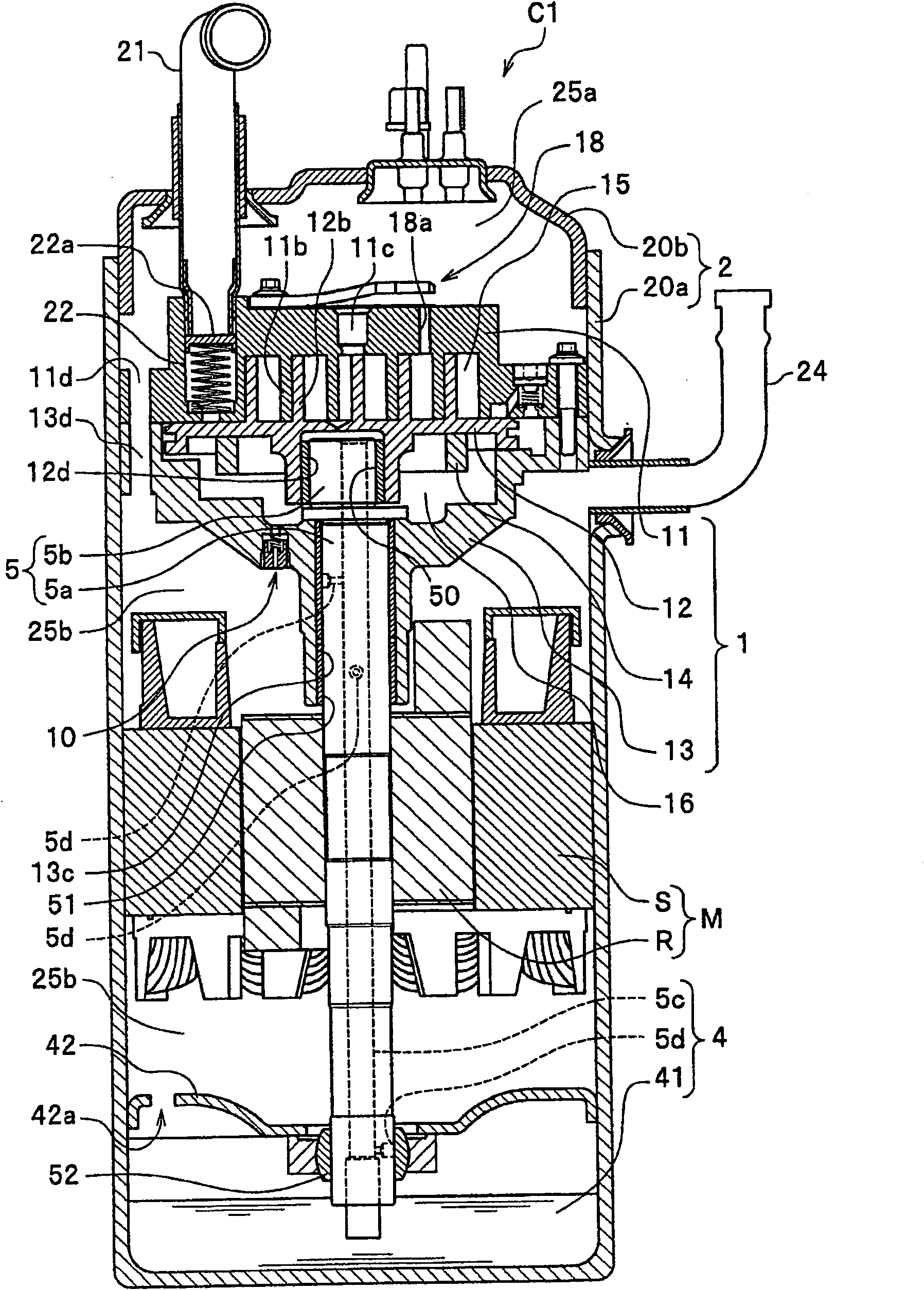
[0023] Hereinafter, embodiments of the present invention will be described in detail with reference to the drawings as appropriate. Here, a scroll compressor used in an air conditioner will be described as an example.

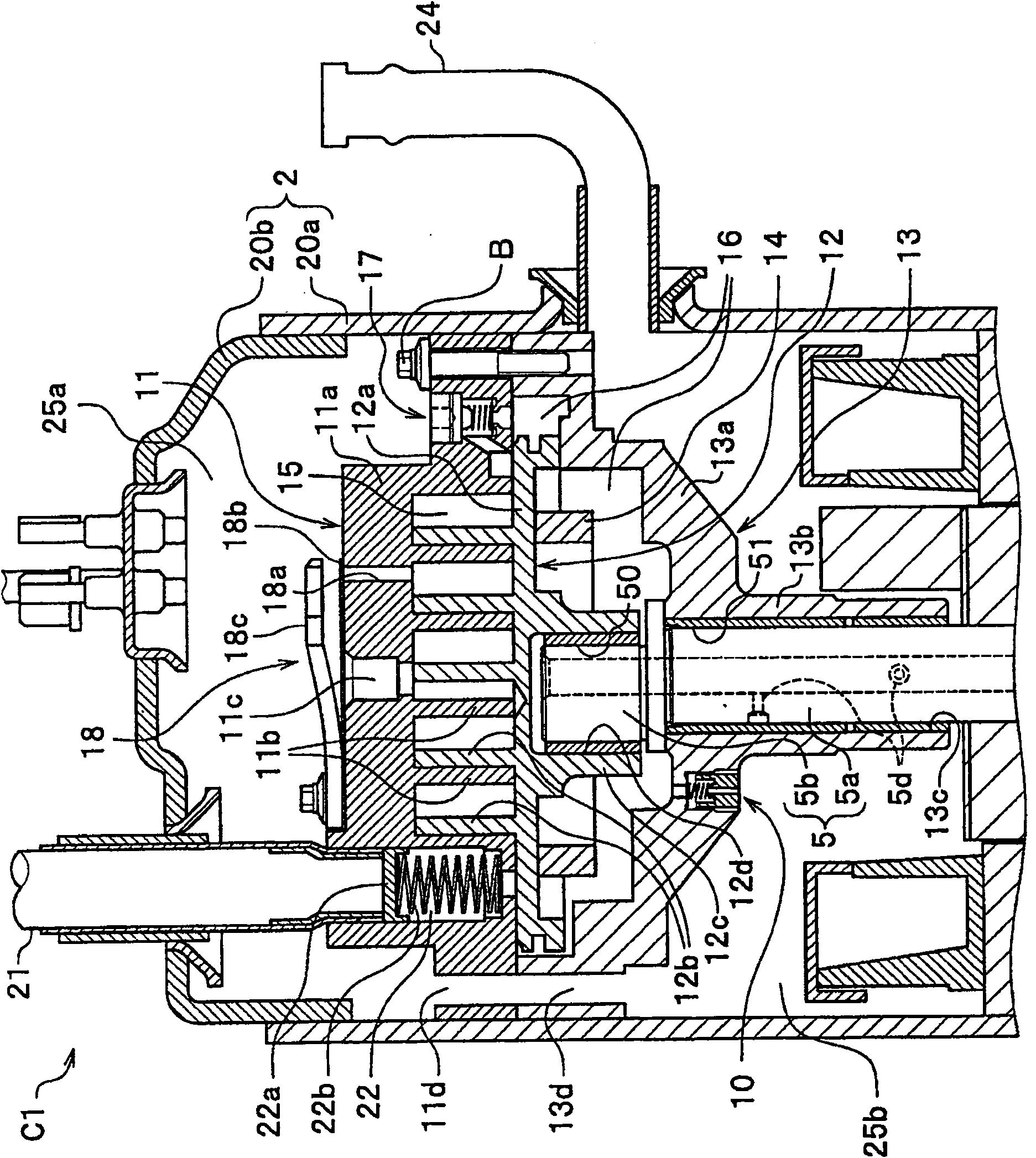
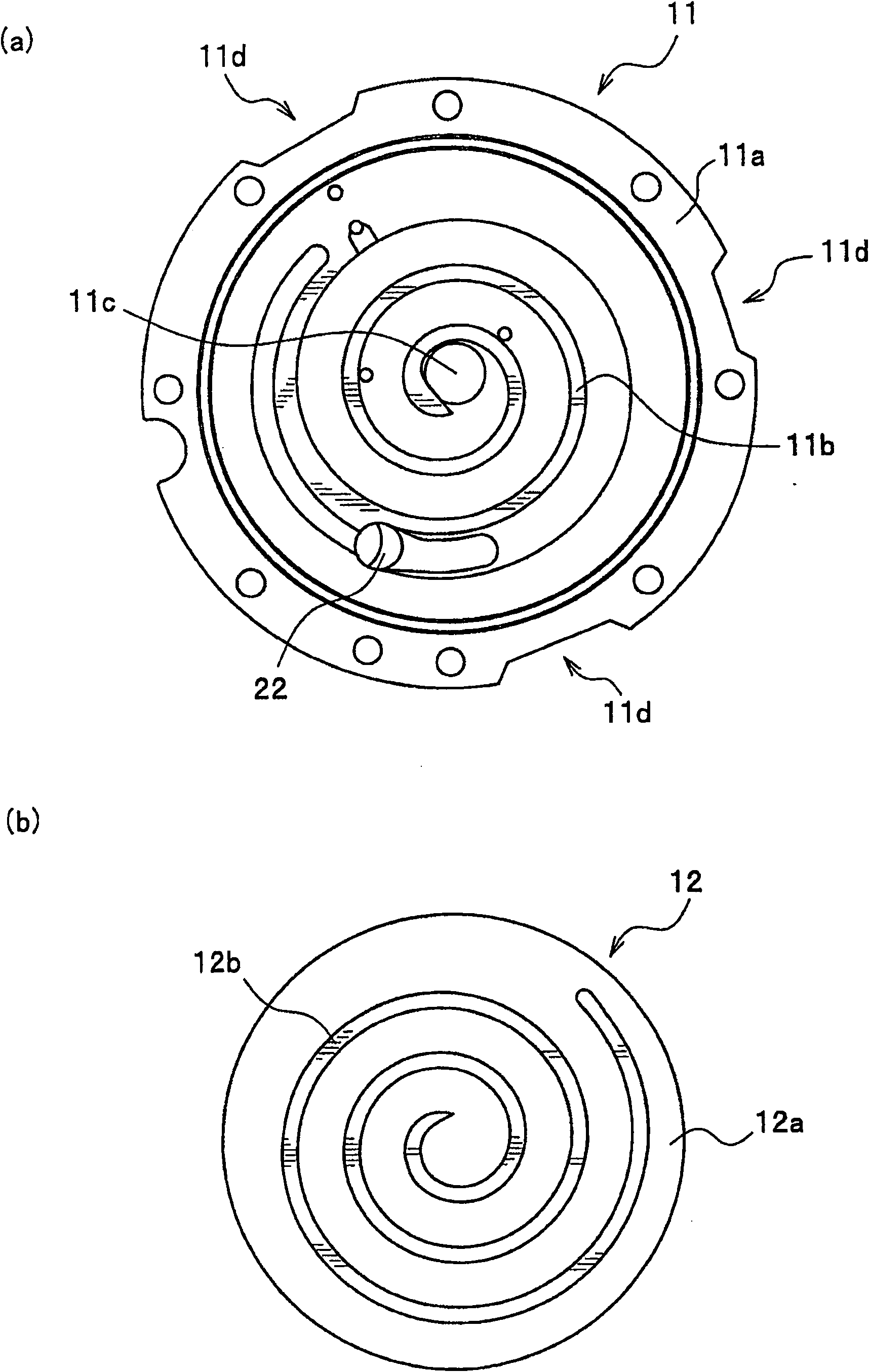
[0024] In the reference figure, figure 1 is a longitudinal sectional view of the scroll compressor of the embodiment; figure 2 will be figure 1 A partially enlarged longitudinal sectional view of the compression mechanism of the scroll compressor shown; image 3 (a) is a plan view showing a state in which the fixed scroll is viewed from the side of the scroll cover plate, image 3 (b) is a plan view showing a state in which the orbiting scroll is viewed from the side of the scroll cover; Figure 4 is a longitudinal sectional view of the back pressure control valve device; Figure 5 (a) is a longitudinal sectional view of the back pressure safety valve device, Figure 5 (b) is a plan view showing a state in which the back pressure relief valve device is v...


PUM


Abstract

A scroll compressor is provided to lower back pressure, which is raised beyond a pressure of a discharge pressure space by installing a back pressure relief valve to discharge pressure of a back pressure chamber into the discharge pressure space. A scroll compressor comprises a closed container(2) including discharge pressure spaces(25a,25b), a fixed scroll(11) fixed to the inside of the closed container, a revolving scroll(12) and a back pressure chamber(16). The revolving scroll engages with the fixed scroll to form a compression chamber(15). The revolving scroll discharges refrigerant, which is pressurized in the compression chamber, into the discharge pressure space through a rotating movement. The revolving scroll is provided with the back pressure chamber in opposition to the fixed scroll. A back pressure relief valve apparatus(10) is installed in the closed container.

Description

technical field [0001] The present invention relates to scroll compressors. Background technique [0002] A general scroll compressor has a fixed scroll and an orbiting scroll that mesh with each other in a closed container, and the scroll-shaped cover (lap) of the fixed scroll and the scroll-shaped cover of the orbiting scroll interact with each other combined to form a compression chamber. In such a scroll compressor, if the orbiting scroll rotates (revolves) relative to the fixed scroll without rotating, the refrigerant is supplied to the compression chamber from a predetermined suction pipe at a predetermined suction pressure. are compressed at the same time. Then, the refrigerant compressed to a predetermined discharge pressure is once discharged from the compression chamber to the discharge pressure space in the closed container, and then sent out of the closed container from the discharge pressure space through a predetermined discharge pipe. [0003] Conventionall...

Claims


Application Information

Patent Timeline
Patent Type & Authority Patents(China)
IPC IPC(8): F04C18/02F04C29/00F04C28/24
CPCF04C18/0215F04C28/24F04C29/0021F04C29/128F04C2210/26F04C2240/30Y10S415/00Y10S417/00
Inventor 松永和行中田裕吉寺井利行
Owner HITACHI JOHNSON CONTROLS AIR CONDITIONING INC
Learn More