Method and system for implementing calling control

A technology for call control and call connection, applied in the field of communication, can solve the problems of difficulty and high cost of monitoring voice channels, and achieve the effects of low cost and easy implementation.

Inactive Publication Date: 2009-10-14
HUAWEI TECH CO LTD
View PDF3 Cites 0 Cited by
  • Summary
  • Abstract
  • Description
  • Claims
  • Application Information

AI Technical Summary

Problems solved by technology

[0004] The purpose of the present invention is to provide a method and system for implementing call control, so as to solve the problem of difficulty and high cost in the existing technology of monitoring the voice channel by a signaling processing device without relay resources

Method used


Image

  • Method and system for implementing calling control
  • Method and system for implementing calling control
  • Method and system for implementing calling control

Examples


Embodiment Construction

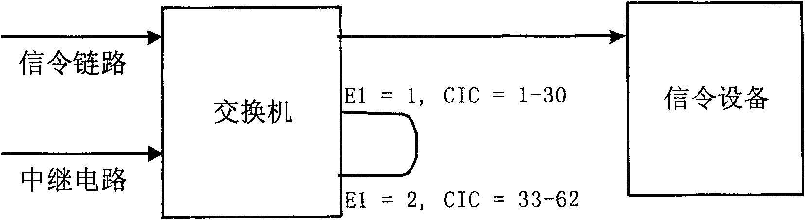
[0023] refer to figure 1 As shown, the signaling processing device has ISDN user part (ISUP) or telephone user part (TUP) signaling protocol processing capability, but it does not need relay resources, and a switch cooperates to realize call processing capability.

[0024] On the switch, perform an E1 self-loop on the trunk corresponding to the office direction of the signaling processing device, that is, interconnect the first and second E1 interfaces. For example, correspondingly map trunk circuits 1 to 30 in the first E1 on the switch side to trunk circuits 33 to 62 in the second E1, even if the incoming voice from circuit identification code (CIC)=1 will From CIC=33, similarly, the relay circuit with CIC=2 will correspond to the relay circuit with CIC=34, and so on.

[0025] For a call from the switch to the signaling processing device, the voice information will return to the switch side through the self-loop E1 channel, and will not pass through the signaling processing...


PUM


Abstract

The invention discloses a method and a system for realizing call control, which are used for enabling the signaling processing equipment without relay resources to have the voice path control capability. The method is to map the trunk circuit of the first E1 interface in the switch that cooperates with the signaling processing equipment to the trunk circuit of the second E1 interface to form a self-loop, and connect the call according to the following steps: The call to the called number is connected to the switch; the call is connected to the signaling processing device by the switch, and the first trunk circuit of the first E1 interface is selected for this call; the signaling processing device converts the called number, The call to the called number is connected to the switch, and an offset is added to the circuit identification code CIC of the first trunk circuit to determine the second trunk circuit allocated for the call. The offset is The CIC interval between the first E1 interface and the second E1 interface; the switch transmits the voice information between the calling party and the called party through the self-loop path.

Description

technical field [0001] The present invention relates to the communication field, in particular to a method and system for realizing call control. Background technique [0002] In the current communication network, switches (including fixed switches and mobile switches) are devices for call origination, connection and termination. At present, switches generally use the ISDN User Part (ISUP) signaling protocol to control calls and provide corresponding Relay circuit resources to complete the transmission of voice information. [0003] With the development of business, in the service processing scheme of called number change, some signaling processing devices are required to be able to process the initialization address message (IAM message) of ISUP protocol, and change the called number by modifying the called number in the IAM message , and at the same time monitor the subsequent messages of the ISUP call flow to achieve the purpose of monitoring the entire call. However, b...

Claims


Application Information

Patent Timeline
Patent Type & Authority Patents(China)
IPC IPC(8): H04Q3/52H04L12/26
Inventor 杨国道李祖健陈友军
Owner HUAWEI TECH CO LTD
Why Eureka
Try Eureka