Compound control system for forcing down grinding wheel of sharpening machine for copper billet at constant pressure and at constant power
A compound control and grinding machine technology, which is applied to the parts of grinding machine tools, machine tools suitable for grinding workpiece edges, grinding machines, etc., can solve the problem of poor dynamic characteristics of the system, complex system composition, and the influence of inertial force on the pressing force Large and other problems, to achieve the effect of increasing power control, improving system efficiency, and reducing system heat generation
- Summary
- Abstract
- Description
- Claims
- Application Information
AI Technical Summary
Problems solved by technology
Method used
Image
Examples
Embodiment 1
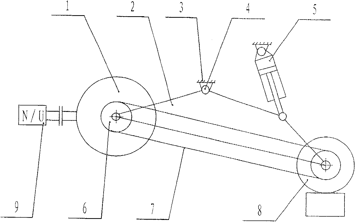
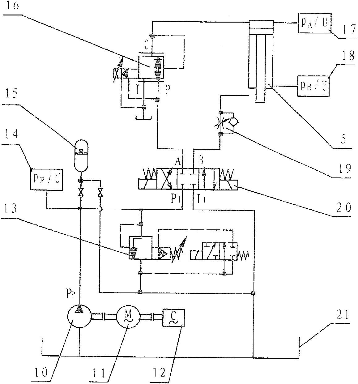
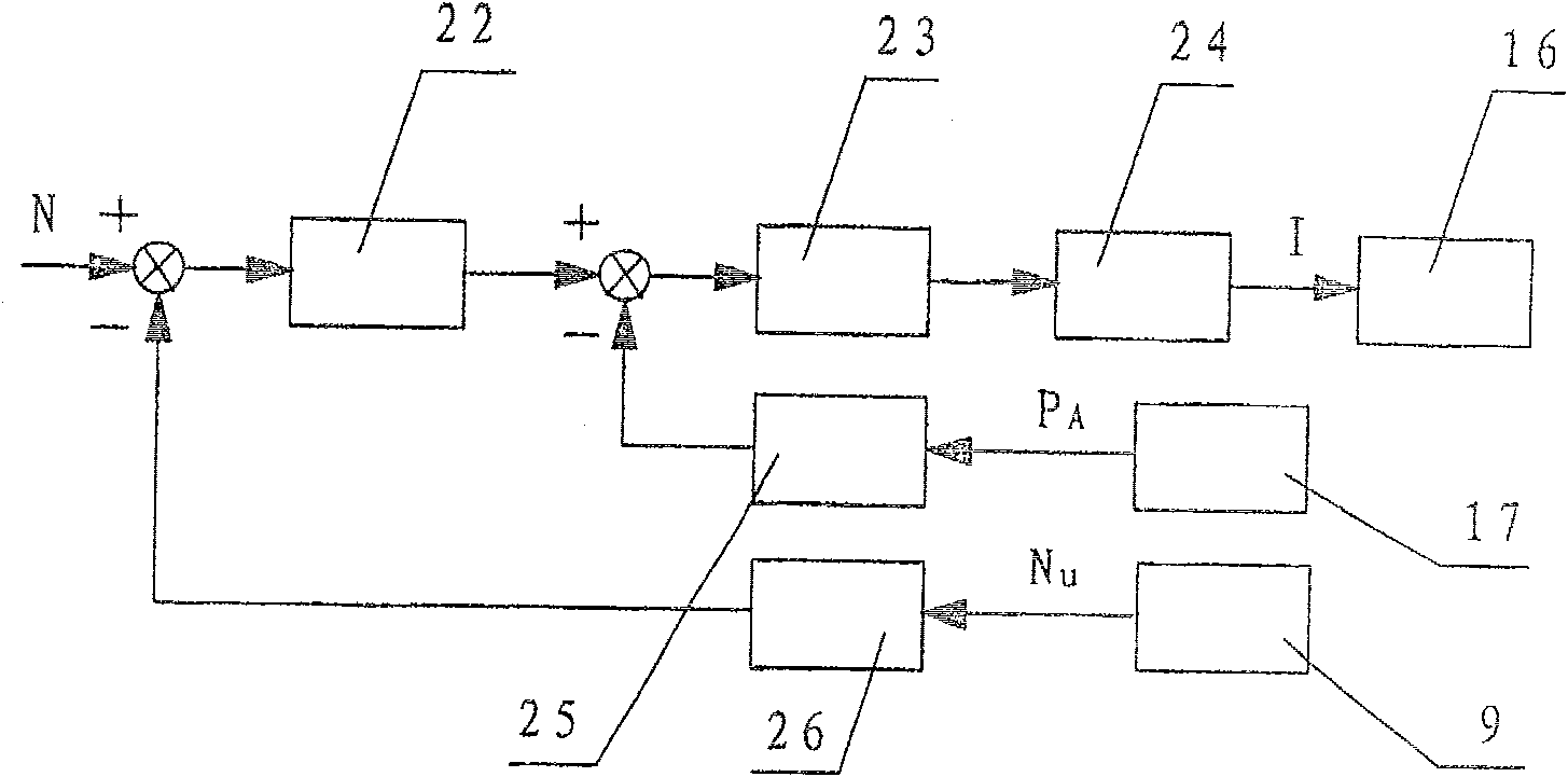
[0015] The utility model relates to a constant pressure and constant power compound control system for grinding wheel of a steel billet grinding machine, which includes a loading device, a hydraulic device and a control device. The loading device is attached figure 1 As shown, it is composed of main motor 1, grinding wheel frame 2, machine base 3, rotating shaft 4, hydraulic cylinder 5, belt pulley 6, belt 7, grinding wheel 8 and the like. Both the main motor 1 and the grinding wheel 8 are installed on the grinding wheel frame 2, and the main motor 1 can also be fixed on the machine base 3; the main motor 1 drives the grinding wheel 8 to rotate through the pulley 6 and the belt 7, and the grinding wheel frame 2 is fixed on the machine base through the rotating shaft 4 3, one end of the hydraulic cylinder 5 is fixed on the base 3, and the other end is connected to the grinding wheel frame 2; the power sensor 9 is used to detect the power of the main motor 1. During the grindin...
Embodiment 2
[0030] Another loading device is composed of a main motor 1, a grinding wheel frame 2, a machine base 3, a rotating shaft 4, a double piston rod hydraulic cylinder 27, a pulley 6, a belt 7 and a grinding wheel 8. The main motor 1 is separated from the grinding wheel frame 2 and fixed on the machine. On the seat 3, the grinding wheel 8 is installed on the grinding wheel frame 2, the main motor 1 is connected with the grinding wheel 8 through the pulley 6 and the belt 7, the grinding wheel frame 2 is fixed on the machine base 3 through the rotating shaft 4, and one end of the double piston rod hydraulic cylinder 27 is fixed on the machine On the seat 3, the other end is connected with the grinding wheel frame 2, and the power sensor 9 is connected with the main motor 1; the hydraulic device is as attached Figure 4 Shown consists of hydraulic pump 10, motor 11, frequency converter 12, electromagnetic overflow valve 13, first sensor 14, accumulator 15, three-way proportional press...
PUM
 Abstract
Description
Claims
Application Information
 - R&D
- Intellectual Property
- Life Sciences
- Materials
- Tech Scout
- Unparalleled Data Quality
- Higher Quality Content
- 60% Fewer Hallucinations
Browse by: Latest US Patents, China's latest patents, Technical Efficacy Thesaurus, Application Domain, Technology Topic, Popular Technical Reports.
© 2025 PatSnap. All rights reserved.Legal|Privacy policy|Modern Slavery Act Transparency Statement|Sitemap|About US| Contact US: help@patsnap.com


