High viscosity fluid microscale spraying glue dropping machine

A spray point and high viscosity technology, which is applied to the device and coating of the surface coating liquid, can solve the problem that the research of high viscosity fluid micro spray technology is still blank, and achieve the effect of high reliability and low cost

Inactive Publication Date: 2009-10-28
HUAZHONG UNIV OF SCI & TECH
View PDF5 Cites 3 Cited by
  • Summary
  • Abstract
  • Description
  • Claims
  • Application Information

AI Technical Summary

Problems solved by technology

However, these dispensing technologies are all contact dispensing technologies, which are suitable for medium-viscosity colloids. The size of the dispensing volume is affected by the gas pressure or motor running time, the geometric parameters of the screw and its matching size with the glue supply chamber, the characteristics of the glue, The influence of parameters such as the distance between the needle and the substrate
At present, the research on high-viscosity fluid micro-injection technology for microelectronic packaging is still blank

Method used


Image

  • High viscosity fluid microscale spraying glue dropping machine
  • High viscosity fluid microscale spraying glue dropping machine

Examples


Embodiment Construction

[0016] The present invention will be described in further detail below in conjunction with the accompanying drawings.

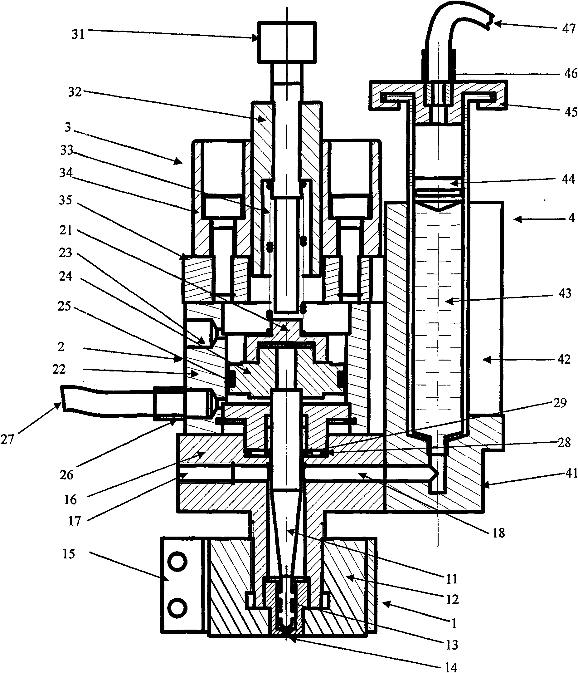
[0017] Such as figure 1 As shown, the present invention consists of four parts: injection mechanism 1, drive mechanism 2, stroke and preload adjustment mechanism 3 and feeding mechanism 4.

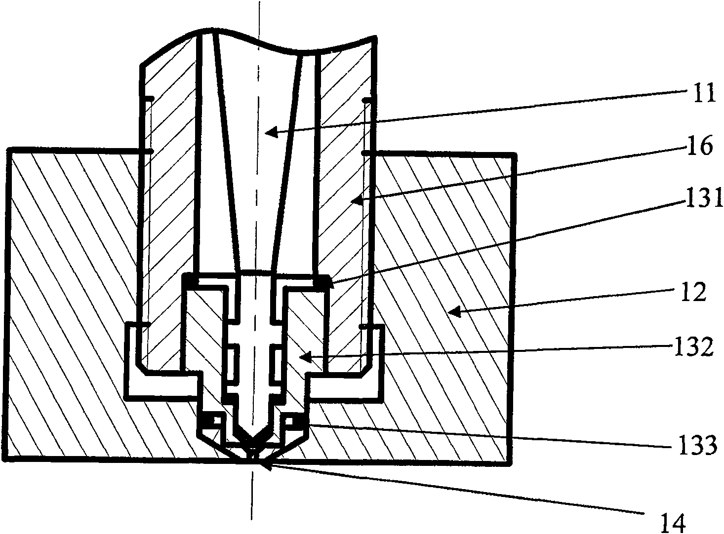
[0018] The injection mechanism 1 includes a cavity 16 and a valve stem 11 arranged inside the cavity 16 , the upper end of the valve stem 11 is connected to the drive mechanism 2 , and the lower end is provided with a spray head 13 . A feed channel 18 is provided on the side of the cavity 16, one end of which communicates with the feeding mechanism 4, and the other end communicates with the gap between the cavity 16 and the valve stem 11, for passing the fluid from the feeding mechanism 4 through The valve stem 11 is conveyed to the injection head 13 . An exhaust channel 17 is also provided on the side of the cavity 16 for exhausting the air in the injection mechanism 1...


PUM


Abstract

The invention provides a high-viscosity fluid micro-jet dispensing device, the upper end of the driving mechanism is connected with the stroke and pre-pressure adjustment mechanism, the lower end is connected with the injection mechanism, the side of the injection mechanism is connected with the feeding mechanism, and a valve rod is arranged inside the injection mechanism And the spray head located at the lower end of the valve stem, the spray head includes a valve stem, a valve seat and a nozzle. When dispensing, the valve stem is separated from the valve seat under the action of the driving mechanism, and the fluid fills the gap formed by the valve stem leaving the valve seat under the action of the supply pressure, and then the compressed air is released, under the action of the stroke and preload adjustment mechanism The fluid around the valve stem and in the valve seat flows to the nozzle at a certain speed, and finally when the valve stem and the valve seat are completely in contact with each other, the fluid stops flowing to the nozzle, and the fluid flowing out of the nozzle is separated from the fluid in the valve seat to form droplets with a certain speed . The invention realizes the distribution of high-viscosity fluid materials, and has the advantages of non-contact, high precision, high reliability, low cost and the like.

Description

technical field [0001] The invention relates to microelectronic packaging technology, in particular to high-viscosity fluid micro-injection technology. Background technique [0002] In microelectronic packaging, the surface coating of encapsulant is a very important process, which is widely used in the subsequent packaging process of integrated circuit manufacturing. The dispensing technologies currently used for encapsulants are mainly divided into two categories: contact type represented by screen printing and needle tube transfer, and non-contact type represented by jetting technology. Most of the encapsulation adhesives used in microelectronic packaging are high-viscosity non-Newtonian fluids, whose complex and changeable characteristics make it difficult to guarantee the coating performance and quality of encapsulation adhesives by contact dispensing. With the transfer of the global semiconductor industry to China, the domestic electronic packaging industry is booming,...

Claims


Application Information

Patent Timeline
Patent Type & Authority Patents(China)
IPC IPC(8): B05C5/00
Inventor 张鸿海刘华勇舒霞云徐裕力肖峻峰朱福龙张丰王永先
Owner HUAZHONG UNIV OF SCI & TECH
Why Eureka
Try Eureka