Splicing Device Used For Splicing Cord Thread Straps

A splicing device, technology of cord belts, applied in the direction of applications, household appliances, winding strips, etc.

Active Publication Date: 2015-06-24
KARL EUGEN FISCHER GMBH
View PDF6 Cites 9 Cited by
  • Summary
  • Abstract
  • Description
  • Claims
  • Application Information

AI Technical Summary

Problems solved by technology

However, this goal cannot always be achieved due to the frequently fluctuating cord strip widths, wherein, of course, also due to the cord strips (for example newly to be spliced, or for example previously spliced ​​and pulled out of the entire blind). Conveyance of cord strips for cord tapes), slight lateral movement possible
Although a very high dimensional stability can already be achieved with the system known from DE 43 09 013 A1, occasionally excessive misalignments occur which are not always acceptable

Method used


Image

  • Splicing Device Used For Splicing Cord Thread Straps
  • Splicing Device Used For Splicing Cord Thread Straps
  • Splicing Device Used For Splicing Cord Thread Straps

Examples


Embodiment Construction

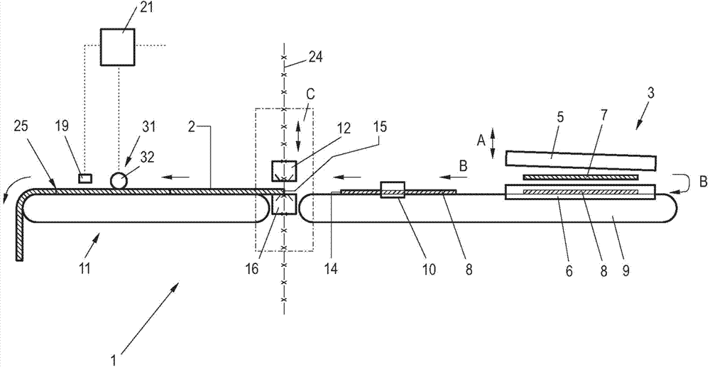
[0037] figure 1 A possible embodiment of the splicing device 1 according to the invention is shown in schematic diagram form for joining cord tape sections to form a cord tape 2 . The cord strip material is drawn as calendered material from a coil which is not shown in detail. Adjoined upstream of the splicing device 1 is a cutting device 3 as well as a receiving and conveying device 9 connected downstream of the cutting device, shown here only schematically, by means of which the cut cord strips are received and conveyed to Splicing device 1. Only the central components required for the understanding are shown, other components such as device holders, linear guides, drives etc. are not shown in detail for reasons of clarity.

[0038] In the example shown, the cutting device 1 is shown as a shear with an upper knife 5 and a lower knife 6 , wherein, as indicated by the double arrow A, the upper knife is moved downwards for cutting. As described in German patent application D...


PUM


Abstract

The present invention relates to a splicing device used for splicing cord thread straps, especially the wirecord fabrics or fabrics. The splicing device comprises a splicing unit and an alignment device connected at the upstream of the splicing unit. In the splicing unit, the front edges of the transmitted cord thread straps are spliced with the back edges of the previously spliced cord thread straps in an area at an edge side, thereby forming the spliced cord thread straps. The alignment device enables the to-be-spliced cord thread straps to move in a direction transverse with the transmission direction, wherein at least two measuring devices (19, 19a, 19b) used for detecting the corresponding extension directions of the two longitudinal edges (22a, 22b) of the spliced cord thread straps are connected at the downstream of the splicing unit, the offset (27a, 27b) of the longitudinal edges in the area 25 can be determined according to the individual detection results and with the help of a control processing device 21, and the control processing device can control the alignment device to correct the offset according to the detection results.

Description

technical field [0001] The invention relates to a splicing device for splicing cord strips, especially steel cords or fabric cords. The splicing device comprises a splicing unit. The trailing edges of the spliced ​​cord strips are spliced ​​in the region of the edge sides to form a spliced ​​cord strip, the splicing device further comprising a splicing unit connected upstream, moving the newly to-be-spliced ​​cord strip transversely to the conveying direction Alignment device for strips. Background technique [0002] This type of splicing device is used to manufacture long cord strips, which are produced from several individual cord strips interconnected by splicing. The connection is effected by a butt joint, wherein the two edges to be joined abut against each other end-to-end. Alternatively, a lap joint is also possible, in which two edges are arranged one above the other. The cord strips are produced beforehand by cutting the cord strips drawn from the coil by means o...

Claims


Application Information

Patent Timeline
Patent Type & Authority Applications(China)
IPC IPC(8): B29D30/38B65H21/00B65H19/18
CPCB65H23/0322B65H2404/7412B65H2404/742B65H2511/512B65H2553/51B65H2601/272B65H2801/93B65H2513/10B65H2220/03B65H2220/01
Inventor M·贝尔
Owner KARL EUGEN FISCHER GMBH
Why Eureka
Try Eureka