Methods and systems for correcting image misalignment

a technology of image misalignment and method, applied in the field of image processing, can solve the problems of insufficient use of method to adequately correct image misalignment, inability to compensate for misalignment caused, and spatial shift of tissue within the image frame field, etc., to achieve the effect of improving optical diagnosis and assessmen

Inactive Publication Date: 2007-06-28
LUMA IMAGING CORP
View PDF6 Cites 15 Cited by
  • Summary
  • Abstract
  • Description
  • Claims
  • Application Information

AI Technical Summary

Benefits of technology

[0006] The invention provides methods of correcting misalignments between sequential images of a sample. The invention is particularly useful for correcting image misalignment due to movement of the sample between images and / or during image acquisition. The invention also allows for real-time, dynamic image alignment for improved optical diagnosis and assessment.
[0007] In a preferred embodiment, the invention comprises determining an x-displacement and a y-displacement corresponding to a misalignment between two images of a tissue sample, where the misalignment is caused by a shift in the position of the sample with respect to the image frame field. For example, in obtaining a sequence of images of an in-situ tissue sample, an embodiment of the invention makes it possible to correct for small image misalignments caused by unavoidable patient motion, such as motion due to breathing. It has been discovered that validating misalignment corrections improves the accuracy of diagnostic procedures that use data from sequential images, particularly where the misalignments are small and the need for accuracy is great. Thus, methods of the invention comprise validating misalignment corrections by splitting individual images into smaller subimages, determining displacement between these subimages, and comparing the subimage displacements to the overall image displacement. Alternatively, validation may comprise adjusting two images according to a misalignment correction, then determining displacement between corresponding subimages and comparing these displacements with a threshold maximum value.
[0008] It has also been discovered that application of a chemical contrast agent, such as acetic acid, prior to or during acquisition of a sequence of tissue images enhances the detection of small-scale image misalignment by increasing intra-image contrast of the tissue images. The enhanced contrast of the tissue features recorded in the images allows for more accurate motion correction determination, since enhanced features may serve as landmarks in determining values of displacement.
[0009] Both misalignment correction determination and validation may be performed such that an accurate adjustment is made for a misalignment before an entire sequence of images is obtained. This allows, for example, “on the fly” adjustment of a camera while a diagnostic exam is in progress. Thus, corrections may be determined, validated, and accurately adjusted for as misalignments occur, reducing the need for retakes and providing immediate feedback as to whether an examination is erroneous. Automatic adjustment may be accomplished by adjusting aspects of the optical interrogation of the sample using a misalignment correction value. Adjustments may be performed, for example, by adjusting aspects of transmission and / or reception of electromagnetic energy associated with the sample. This may include, for example, transmitting a correction signal to a galvanometer system or a voice coil to “null out” a misalignment by adjusting the position of a mirror or other component of the camera obtaining the images according to the correction signal. Alternatively, or additionally, adjustments may be performed by electronically adjusting an aspect of an image, for example, the frame and / or bounds of an image, according to a misalignment correction value, or by performing any other appropriate adjustment procedure.
[0012] A misalignment correction determination may be inaccurate, for example, due to any one or a combination of the following: non-translational sample motion such as rotational motion, local deformation, and / or warping; changing features of a sample such as whitening of tissue; and image recording problems such as focus adjustment, missing images, blurred or distorted images, low signal-to-noise ratio, and computational artifacts. Validation procedures of the invention identify such inaccuracies. The methods of validation may be conducted “on-the-fly” in concert with the methods of determining misalignment corrections in order to improve accuracy and to reduce the time required to conduct a given test.
[0013] Once an image misalignment is detected, an embodiment provides for automatically adjusting an optical signal detection device, such as a camera. For example, a camera may be adjusted “on-the-fly” to compensate for misalignments as images are obtained. This improves accuracy and reduces the time required to conduct a given test.

Problems solved by technology

During this type of diagnostic procedure, the tissue may move while images are being taken, resulting in a spatial shift of the tissue within the image frame field.
However, this method accounts for certain gross movements of a video camera—in particular, certain vibrations caused by the operator of a handheld camcorder.
The method does not compensate for misalignment caused by movement of a sample.
For example, such a method could not be used to adequately correct an image misalignment caused by the small-scale movement of a patient during a diagnostic procedure.
These types of methods cannot be used to correct misalignments caused by the movement of a sample.

Method used


Image

  • Methods and systems for correcting image misalignment
  • Methods and systems for correcting image misalignment
  • Methods and systems for correcting image misalignment

Examples


Embodiment Construction

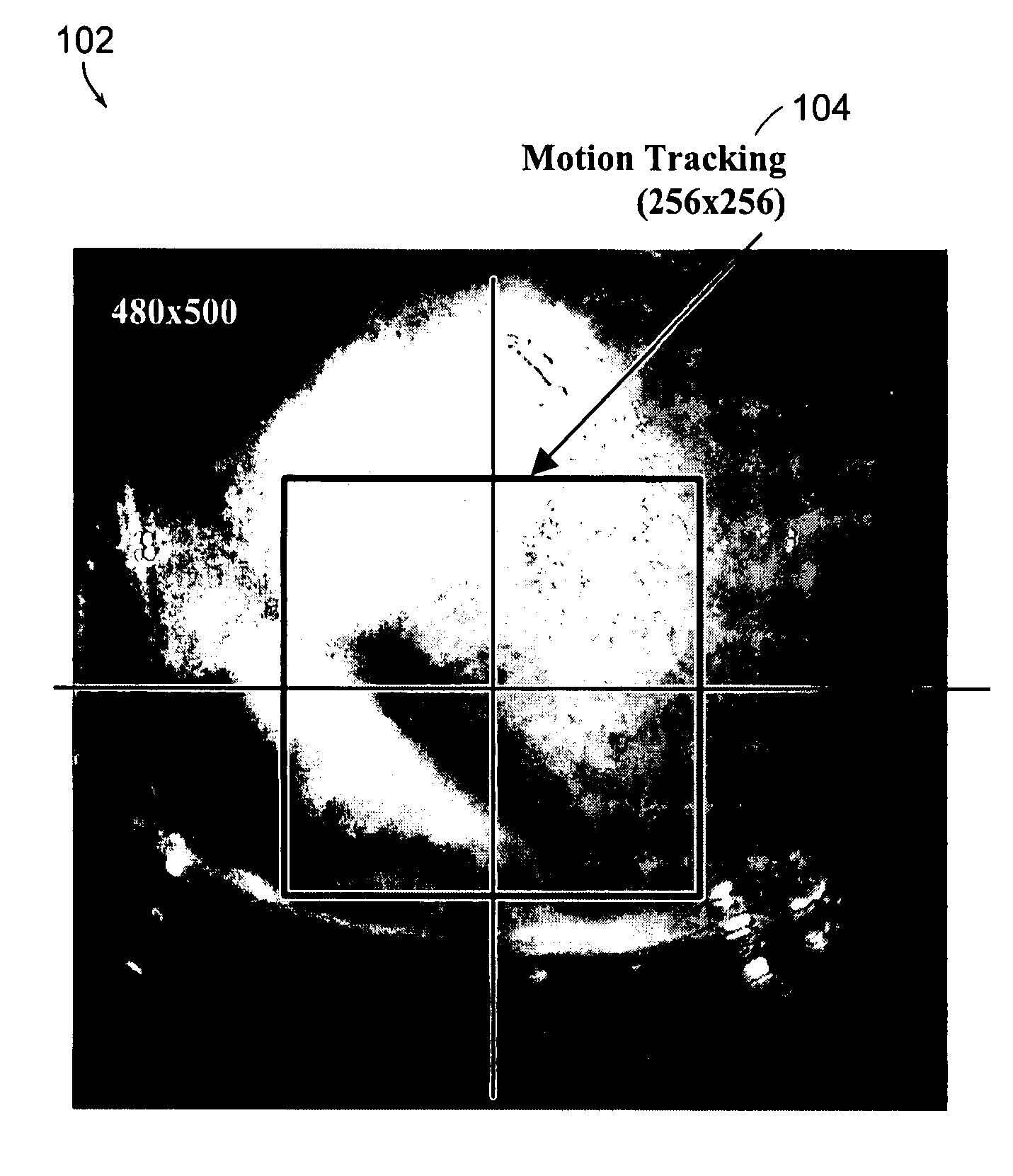
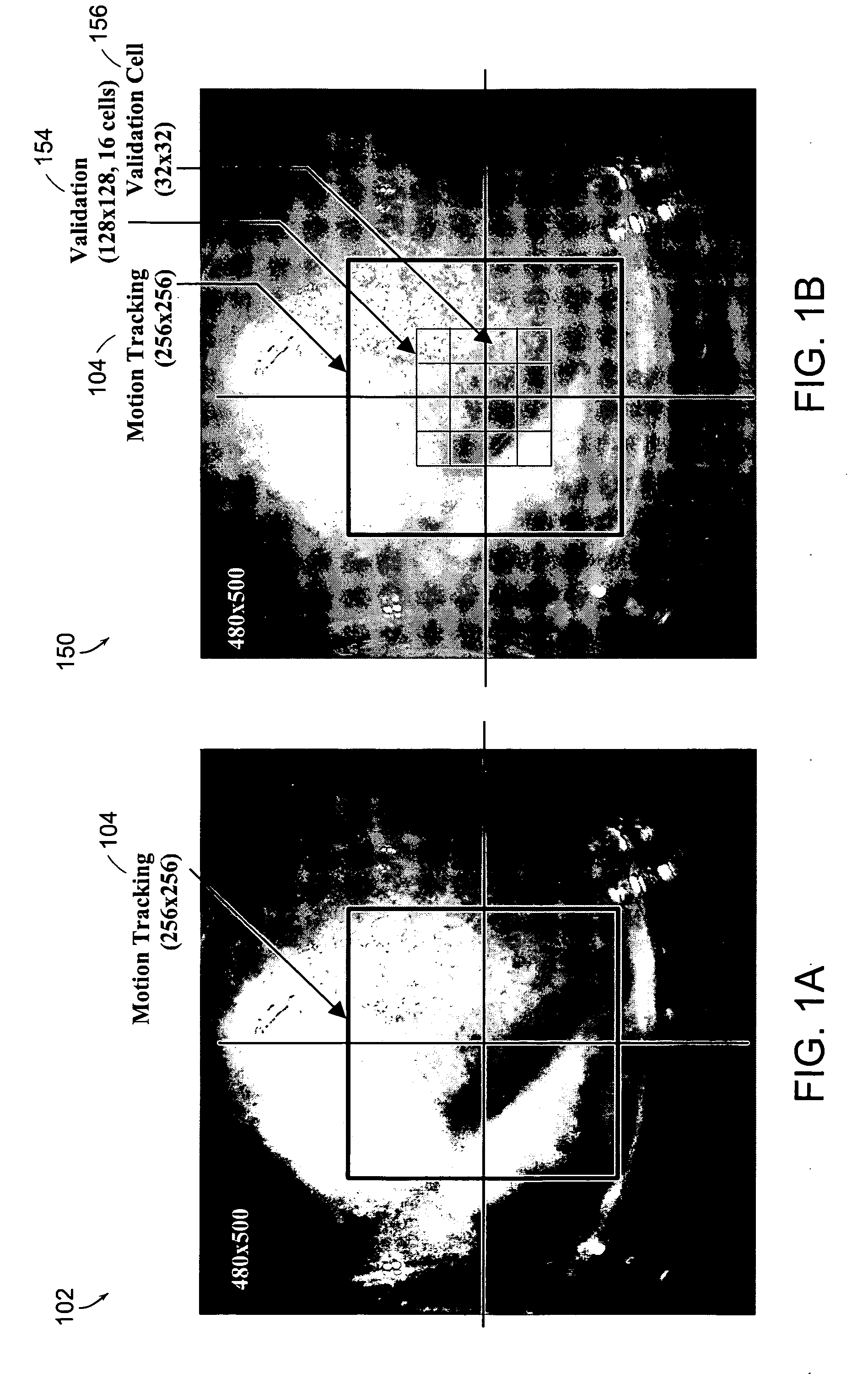
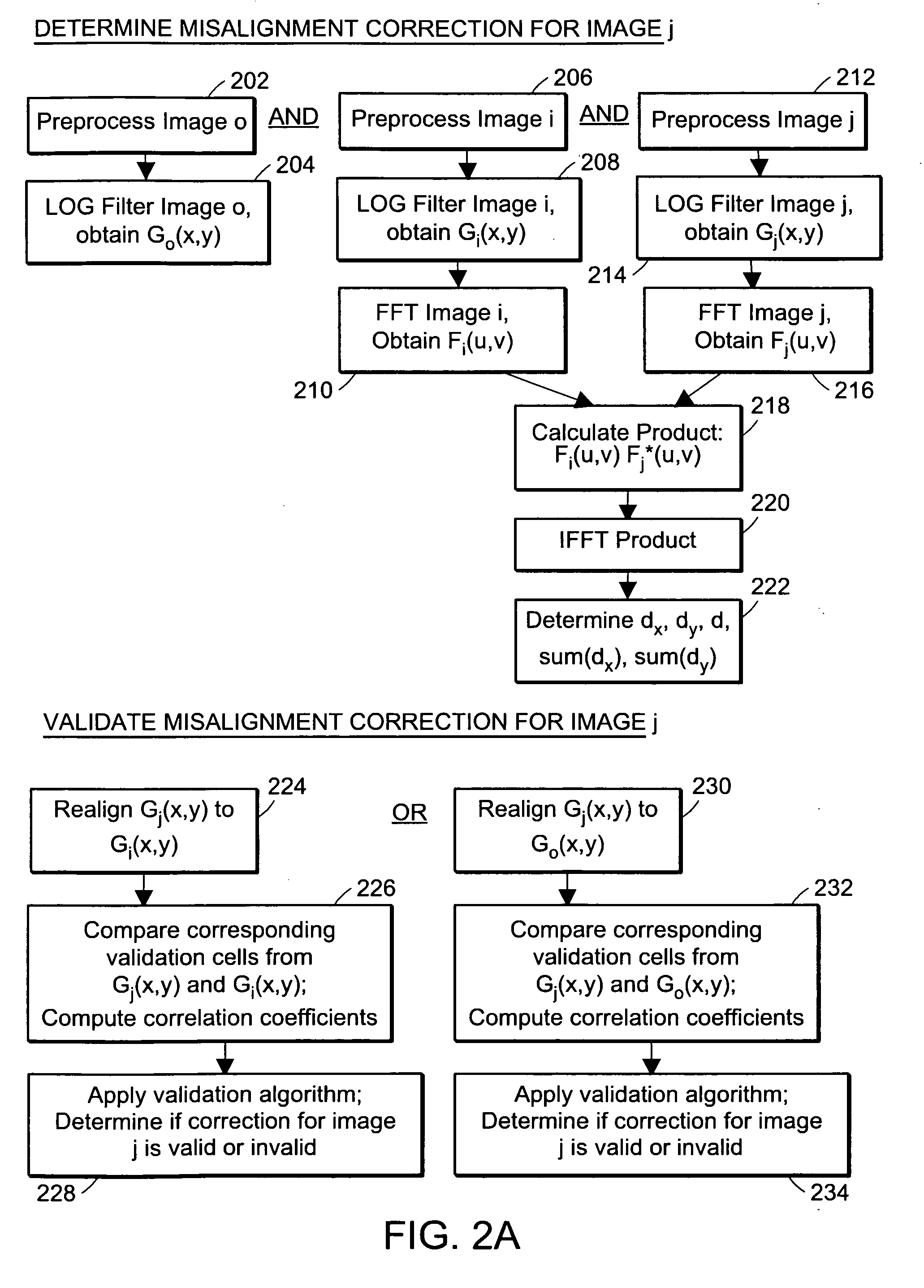
[0040] In general, the invention provides methods of determining a correction for a misalignment between images in a sequence due to movement of a sample. These methods are useful, for example, in the preparation of a sequence of images for analysis, as in medical diagnostics.

[0041] In some diagnostic procedures, methods of the invention comprise applying an agent to a tissue in order to change its optical properties in a way that is indicative of the physiological state of the tissue. The rate and manner in which the tissue changes are important in the characterization of the tissue.

[0042] Certain embodiments of the invention comprise automated and semi-automated analysis of diagnostic procedures that have traditionally required analysis by trained medical personnel. Diagnostic procedures which use automatic image-based tissue analysis provide results having increased sensitivity and / or specificity. See, e.g., co-owned U.S. patent application Ser. No. 10 / 099,881, filed Mar. 15, 2...


PUM


Abstract

The invention provides methods of determining a correction for a misalignment between at least two images in a sequence of images due at least in part to sample movement. The methods are applied, for example, in the processing and analysis of a sequence of images of biological tissue in a diagnostic procedure. The invention also provides methods of validating the correction for a misalignment between at least two images in a sequence of images of a sample. The methods may be applied in deciding whether a correction for misalignment accurately accounts for sample motion.

Description

PRIOR APPLICATIONS [0001] The present application is a continuation-in-part of U.S. patent application Ser. No. 10 / 068,133, filed Feb. 5, 2002, which is a continuation of U.S. patent application Ser. No. 09 / 738,614, filed Dec. 15, 2000, which claims priority to and the benefit of U.S. Provisional Patent Application Ser. No. 60 / 170,972, filed Dec. 15, 1999; the present application also claims the benefit of the co-owned U.S. Provisional Patent Application entitled, “Methods and Systems for Correcting Image Misalignment”, by Schott et al., filed on Sep. 30, 2002, and referenced by attorney docket number MDS-031PR. All of the above applications are assigned to the common assignee of this application and are hereby incorporated by reference.FIELD OF THE INVENTION [0002] This invention relates generally to image processing. More particularly, the invention relates to correcting image misalignment, where the misalignment is due at least in part to sample movement. BACKGROUND OF THE INVENT...

Claims


Application Information

Patent Timeline
Patent Type & Authority Applications(United States)
IPC IPC(8): G06K9/32A61B1/00A61B5/00A61M11/00
CPCA61B1/00009A61B1/0008A61B1/00142A61B1/043A61B5/0071A61B5/0084A61B5/7257A61M11/00G06T7/0036G06T7/206G06T2207/10068G06T2207/20056G06T2207/30004G06T7/37G06T7/262A61B1/000094
Inventor CLUNE, THOMASSCHMID, PHILIPPEJIANG, CHUNSHENG
Owner LUMA IMAGING CORP
Why Eureka
Try Eureka