
Image forming apparatus

a technology of image forming apparatus and forming tube, which is applied in the field of image forming tube, can solve the problems of increased apparatus cost, complicated circuit structure, and inability to adapt, and achieve the effects of increasing image forming ability, improving adaptability, and improving resolution

Inactive Publication Date: 2009-07-30
KONICA MINOLTA BUSINESS TECH INC
View PDF4 Cites 13 Cited by
  • Summary
  • Abstract
  • Description
  • Claims
  • Application Information

AI Technical Summary

Benefits of technology

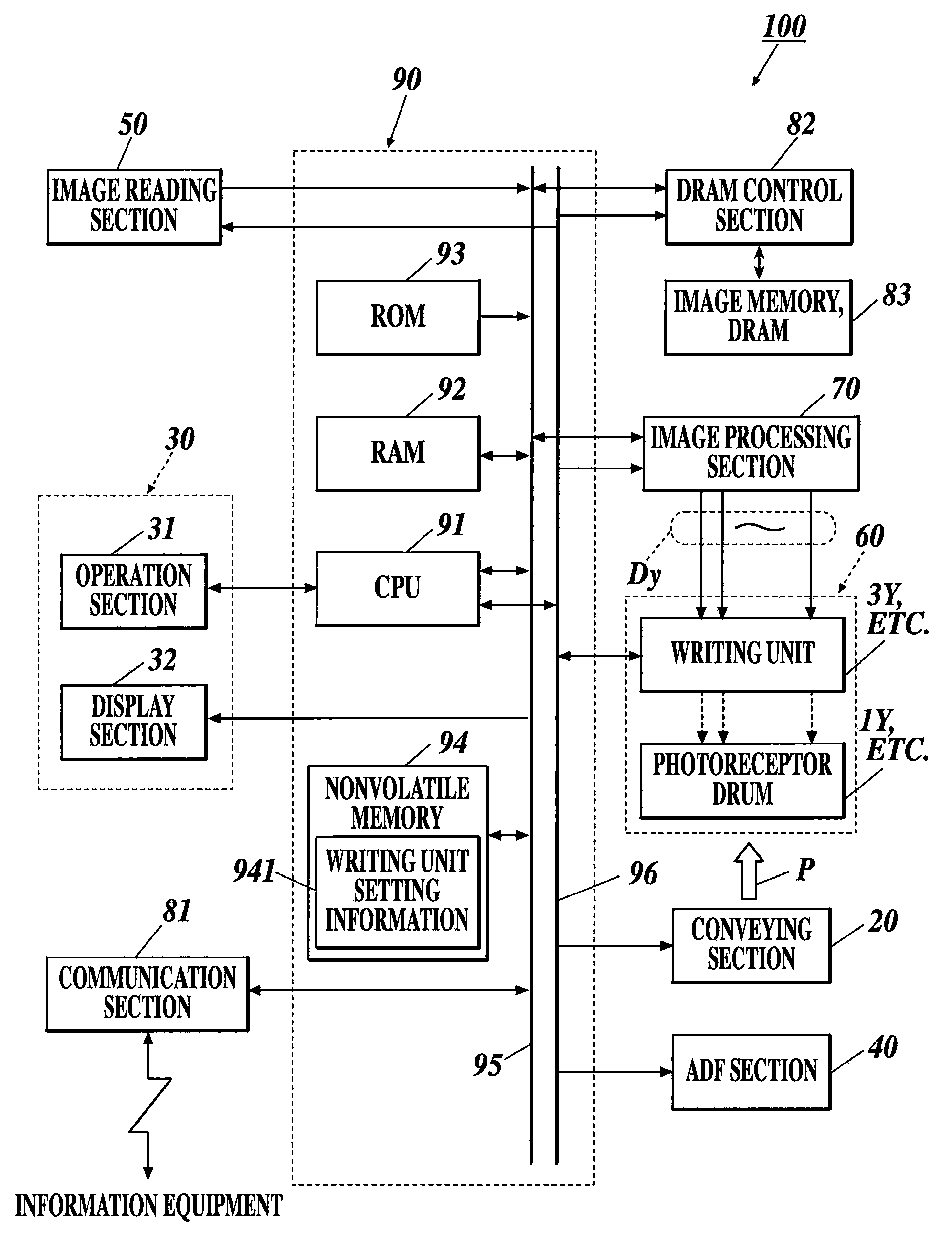
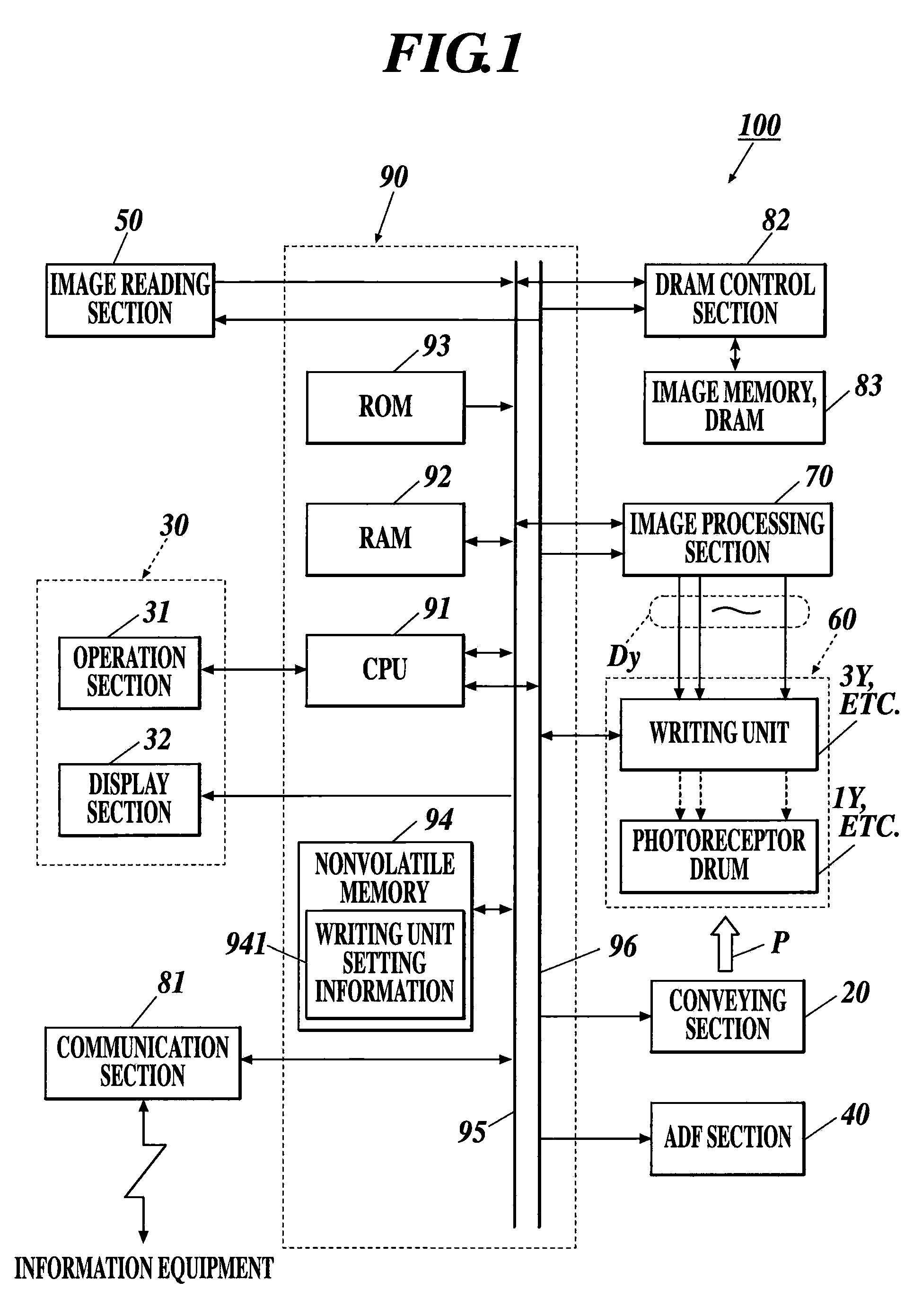
[0022]The present invention has been made in consideration of the above problems, and it is one of main objects to provide an image forming apparatus which can correct misalignment in image forming due to mounting status of a print head or an alignment status of a light-emitting element of the print head, which can easily adapt to increase of image forming ability (higher resolution) and reduce cost of the apparatus.

Problems solved by technology

As a result, problems occur such as increase in cost of the apparatus, complicated circuit structure, etc.
However, the conventional correction processing circuit has the above-described problem and it is not suitable as a means for performing skew correction / bow correction of an image formed with a high resolution.

Method used


Image

  • Image forming apparatus
  • Image forming apparatus
  • Image forming apparatus

Examples


first example

[0162]In the first example, correction of skew due to the mounting status of the LPH is described where the transfer processing of the large capacity memory 723 by the memory controller 722 is performed in the burst access unit of 128 pixels'1 line.

[0163]FIG. 11 is an explanatory diagram showing an example of a specific structure of a fine adjustment processing section 725 used in the first example.

[0164]The fine adjustment processing section 725 shown in FIG. 11 includes three stages of line buffers LB1 to LB3 and selector SEL.

[0165]The line buffer LB1 stores image data burst transferred as (N+1)-th line from the memory controller 722. The line buffer LB2 stores image data burst transferred as N-th line from the memory controller 722. The line buffer LB3 stores image data burst transferred as (N−1)-th line from the memory controller 722.

[0166]According to a selection signal (fine adjustment enable signal) from the fine adjustment signal generation section 724, the selector SEL sele...

second example

[0179]In the second example, correction of skew due to the mounting status of the LPH is described where the transfer processing of the large capacity memory 723 by the memory controller 722 is performed in the burst access unit of 32 pixels×4 lines.

[0180]FIG. 13 is an explanatory diagram showing an example of a specific structure of a fine adjustment processing section 725 used in the second example.

[0181]The fine adjustment processing section 725 shown in FIG. 13 includes three stages of line buffers LB1 to LB3 and selector SEL. The image data throughout the main scanning direction transferred in the burst access unit of 32 pixels×4 lines (hereinafter referred to as one block line) is stored in each line buffer. In other words, the difference from the first example is that four lines of the original image data are stored in one line buffer.

[0182]The line buffer LB1 stores image data burst transferred as (N+1)-th block line from the memory controller 722. The line buffer LB2 stores...


PUM


Abstract

Disclosed is an image forming apparatus including: an image memory to store image data to form an image with pixels aligned in a main scanning direction and a sub-scanning direction; a print head; and a correction section to perform correction processing on the image data to correct misalignment which occurs when an image is formed, wherein the correction section includes: a memory which can perform burst transfer; a first control section; line buffers; and a second control section, wherein the first control section successively writes the image data in the burst access unit in the memory and reads the image data in the burst access unit while controlling the address of the memory according to a first control signal generated based on previously set information concerning correction; and the second control section selects image data to output according to a second control signal generated based on the information.

Description

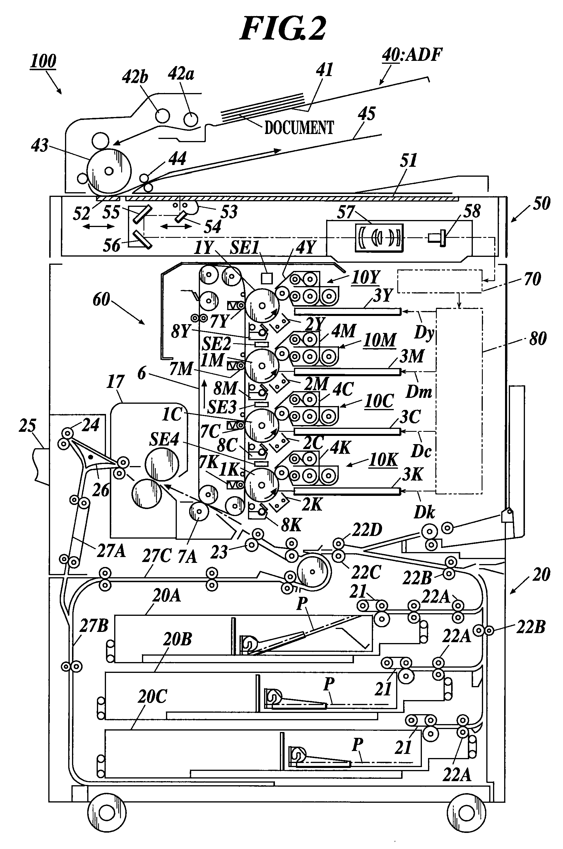
BACKGROUND[0001]1. Field of the Invention[0002]The present invention relates to an image forming apparatus which can correct misalignment in image forming due to mounting status of a print head or an alignment status of a light-emitting element of the print head.[0003]2. Description of Related Art[0004]Generally an image forming apparatus such as a digital multi function peripheral includes an image forming section to form an image on a sheet. The image forming section includes a writing unit as an exposing section, and an electrostatic latent image based on image data is formed by exposing the charged photoreceptor drum with the writing unit.[0005]As a writing unit, for example, a print head such as an LED print head (LPH) is used for forming an image in a line in a main scanning direction which is orthogonal to a conveying direction (sub-scanning direction) of a sheet on which an image is to be formed.[0006]Here, an LPH is a plurality of LED array chips, which are formed with a pl...

Claims


Application Information

Patent Timeline
Patent Type & Authority Applications(United States)
IPC IPC(8): G06K15/00
CPCH04N1/0473H04N1/053H04N1/506H04N2201/04796H04N2201/04789H04N2201/04791H04N2201/04793H04N2201/04787
Inventor SAITO, DAIJIRO
Owner KONICA MINOLTA BUSINESS TECH INC
Learn More