Plate storing body for supplying component and component supplying apparatus

A component supply and component technology, applied in the direction of electrical components, electrical components, conveyor objects, etc., can solve the problems of chip generation, plate 706 shaking, narrow intervals, etc., to prevent chip generation, realize component supply, and effective component supply Effect

Inactive Publication Date: 2007-04-18
PANASONIC CORP
View PDF2 Cites 13 Cited by
  • Summary
  • Abstract
  • Description
  • Claims
  • Application Information

AI Technical Summary

Problems solved by technology

[0007] However, in such a component supply device, when the board is held and taken out from the board box, for example, the board has a substantially disk-like shape, so as shown in the schematic diagram of FIG. When the board 706 is stored in an oblique posture in the take-out direction C, at this time, the peripheral portion of the board 706 may contact (or collide with) the groove portion 750b of the board box 750, and the board 706 may shake.
[0008] In particular, when the plate 706 is a tray supply plate on which a plurality of tray supply components are placed, due to the above-mentioned shaking, each tray supply component placed above may be scattered from the tray supply plate. The following problems: Reliable component supply is hindered, and effective component supply cannot be performed
In addition, if the operator confirms the above-mentioned posture of each board 706 when storing each board 706 in the board box 750, the possibility of such a problem may be reduced, but work time is required for the above-mentioned confirmation. , so it will increase the time required to accommodate each board 706, which will hinder the efficiency of component supply
[0009] In addition, in the panel box 750, since the intervals between the respective grooves 750b are narrowed, when the operator stores the panels 706 in the panel box 750, as shown in the schematic explanatory diagram of FIG. The support and storage of the board 706 by the groove portion 750b of the group, in the board box 750, sometimes it is difficult to accommodate the board 706 through the horizontal support posture (that is, the inclined state)
In this case, there is an obstacle to removing the board 706 from the board box 750, thereby preventing reliable and efficient component supply.
[0010] In addition, in the board case 750 as described above, when the board 706 is accommodated in an inclined support posture and the board 706 is taken out in this state, it is not only difficult to take out the board 706 reliably, but also the grooves of the respective ends of the support board 706 The frictional resistance caused by the contact between 750b and the groove is also larger than when stored in a normal support posture, which will cut off the end of the plate 706 or the groove 750b, resulting in chips
In this case, there is also a problem that the generated swarf may adhere to the surface of the component, which hinders reliable component supply for high-precision component mounting.

Method used


Image

  • Plate storing body for supplying component and component supplying apparatus
  • Plate storing body for supplying component and component supplying apparatus
  • Plate storing body for supplying component and component supplying apparatus

Examples


no. 1 approach

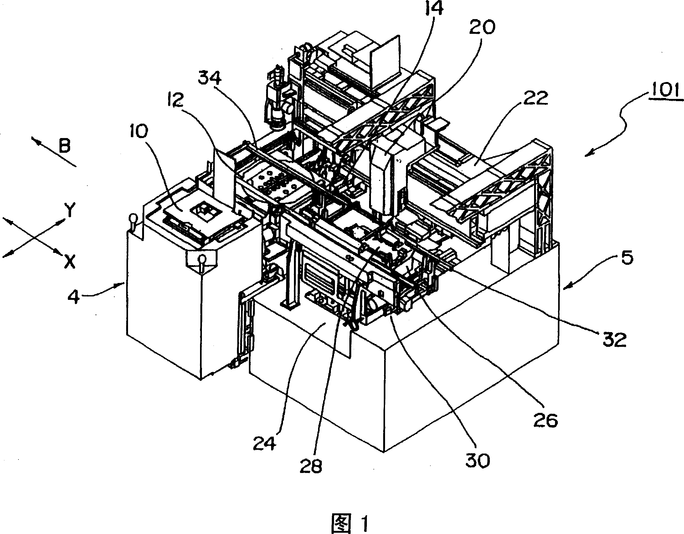
[0107] 1 is a perspective view showing an electronic component mounting device 101 including a component supply device 4 as an example of the component supply device according to the first embodiment of the present invention, and mounting components supplied by the component supply device 4. An example of a component mounting device on a substrate. Before describing the detailed configuration and operation of the component supply device 4 , the overall configuration and operation of an electronic component mounting device 101 including such a component supply device 4 will be described with reference to FIG. 1 .

[0108] (About Electronic Component Mounting Device)

[0109] As shown in FIG. 1 , an electronic component mounting apparatus 101 is a device for mounting an electronic component 2 such as a chip component or a bare IC chip on a substrate as an example of a component, and generally includes a device capable of supplying a plurality of electronic components. 2, and a ...

no. 2 approach

[0178] In addition, this invention is not limited to the said embodiment, It can implement in other various forms. For example, a component supply device according to a second embodiment of the present invention will be described below. In addition, the component supply device of this second embodiment is compared with the component supply device 4 of the above-mentioned first embodiment, although the structure of the parts shown below is different, but its basic structure is common, so in order to facilitate understanding In the following description, the same reference numerals are attached to the same components as those of the component supply device 4 of the first embodiment described above.

[0179] In the component supply device 204 shown in FIG. 21 , the elevating device 10 is provided with a pallet box 250 in which a plurality of the above-mentioned wafer supply boards and a plurality of the above-mentioned tray supply boards are mixed and accommodated. The panel box...

no. 3 approach

[0194] Next, a component supply device according to a third embodiment of the present invention will be described below. Compared with the component supply device 4 of the above-mentioned first embodiment, the component supply device according to the third embodiment has the same basic structure although the parts shown below have different structures. , the same reference numerals are attached to the same structural parts as those of the component supply device 4 of the first embodiment described above.

[0195] FIG. 30 is a schematic explanatory diagram of the board box 450 viewed from the front side, with the board taking-out direction C of the board box 450 included in the component supply device of the third embodiment being the front side.

[0196] As shown in FIG. 30, a plurality of grooves 450b arranged oppositely are formed inside each side wall portion 450a of the board box 450, and each end portion of the plate 6 is supported by each set of opposing grooves 450b, th...


PUM


Abstract

A plurality of components (2) are arranged on a plurality of component supplying plates (6). A plate supplying body (50) stores a plurality of the component supplying plates (6) by stacking them. Among supporting guide parts (50b), supporting guide parts forming a pair can be discriminated from those supporting guide parts forming other pairs. An identifying mark part (114) is visibly formed in the plate supplying direction at an edge part of each supporting guide part or in the vicinity in such direction.

Description

technical field [0001] The present invention relates to a component supply board container (or a board storage unit) and a component supply device capable of accommodating a plurality of component supply boards arranged to supply a plurality of components mounted on a substrate in a stacked manner, and by making the The stored component supply board is moved in a direction along its surface, that is, in a board supply direction, and the component supply board is taken out so that each of the above-described components can be supplied. Background technique [0002] Conventionally, such a component supply board container is called a board box, for example, and is used in a component supply device for supplying components for component mounting. In such a card box, either one of a wafer supply plate on which a plurality of wafer supply elements are arranged among components mounted on a substrate is placed on a wafer supply plate, or a tray supply plate is selectively accommoda...

Claims


Application Information

Patent Timeline
Patent Type & Authority Applications(China)
IPC IPC(8): H05K13/02B65D85/38H01L21/68H01L21/00H01L21/673H01L21/677H01L21/687
CPCH01L21/67383H01L21/67778H01L21/67766H01L21/68785H01L21/67271H01L21/6732H01L21/48
Inventor 成田正力石田贤一平田修一仕田智
Owner PANASONIC CORP
Why Eureka
Try Eureka