Rear separating rolling mechanism of servo motor drived comber

A technology for separating rollers and servo motors, which is used in combing machines, textile and papermaking, fiber processing, etc. The effect of improving yarn quality, reducing intermediate gear transmission links, and improving motion transmission accuracy

Inactive Publication Date: 2009-11-04
SHANGHAI TEXTILE MACHINERY COMPLEX
View PDF5 Cites 0 Cited by
  • Summary
  • Abstract
  • Description
  • Claims
  • Application Information

AI Technical Summary

Problems solved by technology

[0003] Because a servo motor is used to drive two separation rollers, three transmission wheels, and two couplings at the same time, the transmission torque is large and the power consumption is large; there are many meshing points for transmission motion, and the precision is poor; the parts and components of the mechanism are manufactured and The installation requires high precision; it is difficult to adapt to high-speed reciprocating rotation

Method used


Image

  • Rear separating rolling mechanism of servo motor drived comber
  • Rear separating rolling mechanism of servo motor drived comber
  • Rear separating rolling mechanism of servo motor drived comber

Examples


Embodiment Construction

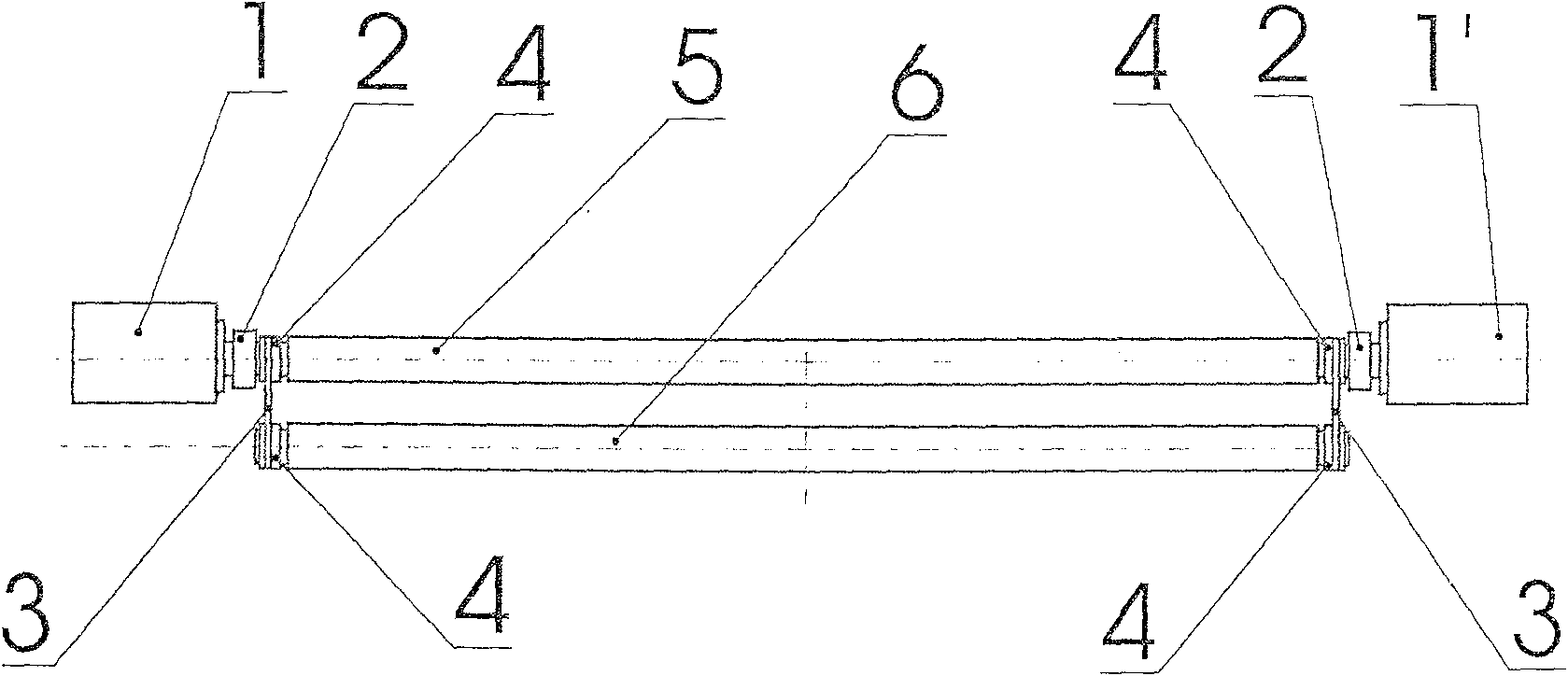
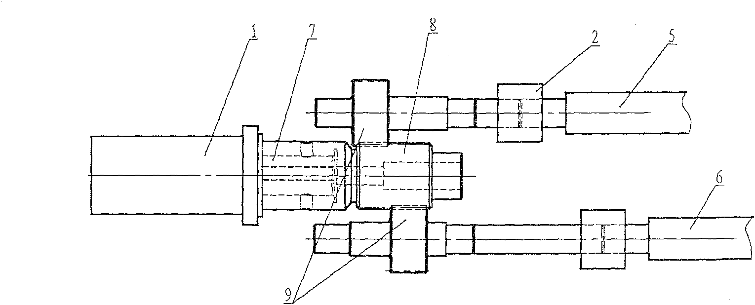
[0018] Such as figure 1 The rear separation roller mechanism of the combing machine driven by the servo motor shown is a creative improvement of the existing separation roller mechanism of the combing machine driven by the servo motor. The specific solution is: two servo motors 1, 1 ′. It is composed of the rear separation roller 5 and the front separation roller 6, characterized in that: the front separation roller 6 and the rear separation roller 5 are each a continuous and complete body, wherein the rear separation roller 5 passes through the The left and right ends are respectively connected to the servo motors 1, 1'controlled by the same drive controller. While driving the rear separation roller, the servo motors 1 and 1'also pass through the two synchronously fixed ends of the rear separation roller. The belt wheel 4 and the set synchronous belt 3 are connected with the synchronous belt wheels 4 fixed at the two ends of the front separating roller 6, and the separating roll...


PUM


Abstract

The present invention relates to a rear separation roller mechanism of a combing machine driven by a servo motor, which is composed of a servo motor, a rear separation roller 5 and a front separation roller 6, and is characterized in that: each of the front separation roller 6 and the rear separation roller 5 is a It is a continuous integral body, wherein, the said rear roller 5 is respectively connected to the servo motors 1, 1' controlled by the same drive controller at its left and right ends, and the servo motors 1, 1' drive the rear The separating roller is connected with the synchronous pulley 4 fixedly installed at both ends of the front separating roller 6 through two synchronous pulleys 4 fixed at both ends of the rear separating roller and the set synchronous belt 3, and the front separating roller is driven; Separation roller servo motor drive mechanism. The mechanism improves the quick response capability of the servo motor by reducing the stand-alone power of the servo motor, and then improves the motion accuracy of the separation roller of the combing machine.

Description

Technical field [0001] The invention relates to a composition mechanism of a cotton combing machine, in particular to a rear separation roller mechanism of the combing machine driven by a servo motor, belonging to the category of textile machinery. Background technique [0002] In the existing multi-axis drive cotton combing machine, the front and rear separating rollers of the combing machine are driven by a servo motor. One end of the front and rear separating rollers is provided with a pair of transmission gears 9 and a transmission gear 8 is installed on the output shaft 7 of the servo motor. Let it mesh with the two transmission gears 9 on the front and rear separating rollers at the same time to transmit the transmission movement to the two separating rollers. [0003] Because it uses a servo motor to drive two separating rollers, three transmission wheels, and two couplings at the same time, the transmission torque is large, and the power consumption is large; the meshing ...

Claims


Application Information

Patent Timeline
Patent Type & Authority Patents(China)
IPC IPC(8): D01G19/06D01G19/10D01G19/26
Inventor 顾丹青王生泽严纪琴严礼根
Owner SHANGHAI TEXTILE MACHINERY COMPLEX
Why Eureka
Try Eureka