
Clutch for a transmission

A clutch and reaction plate technology, used in clutches, friction clutches, mechanical drive clutches, etc., can solve the problems of metal friction materials that are not cost-effective, low torque capacity, and low effectiveness.

Inactive Publication Date: 2009-11-04
GM GLOBAL TECH OPERATIONS LLC
View PDF5 Cites 0 Cited by
  • Summary
  • Abstract
  • Description
  • Claims
  • Application Information

AI Technical Summary

Problems solved by technology

However, sintered metallic friction materials are less cost-effective because the applied load distribution is slightly different for each engagement
Abrasion losses are less effective in avoiding localized overloads than elastic deformations
As the fluid is squeezed between the two entities, as a result of fluid shear, higher local fluid pressures (hard-EHL vs. soft-EHL) cause higher thermal Generated, therefore, even better thermal conductivity may not be sufficient to support the diaphragm, may require a higher kinematic viscosity fluid (with additional loss of efficiency), and result in lower torque capacity

Method used


Image

  • Clutch for a transmission
  • Clutch for a transmission
  • Clutch for a transmission

Examples


Embodiment Construction

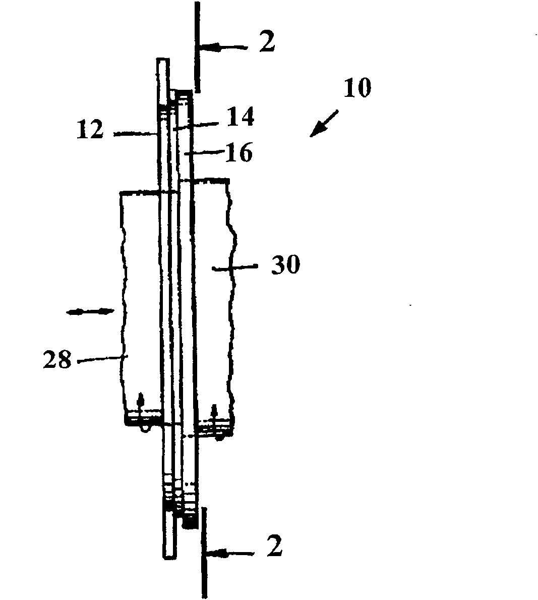
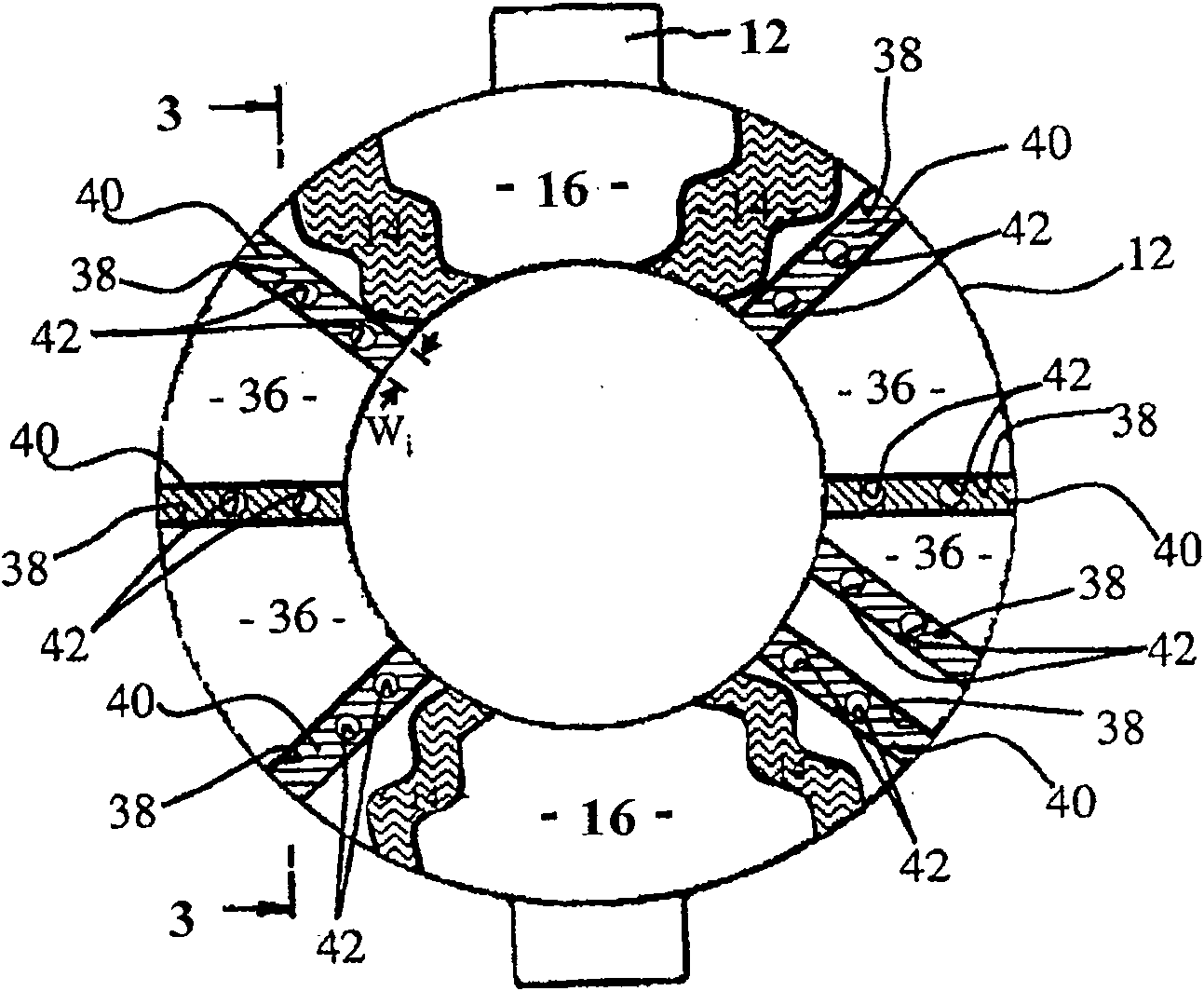
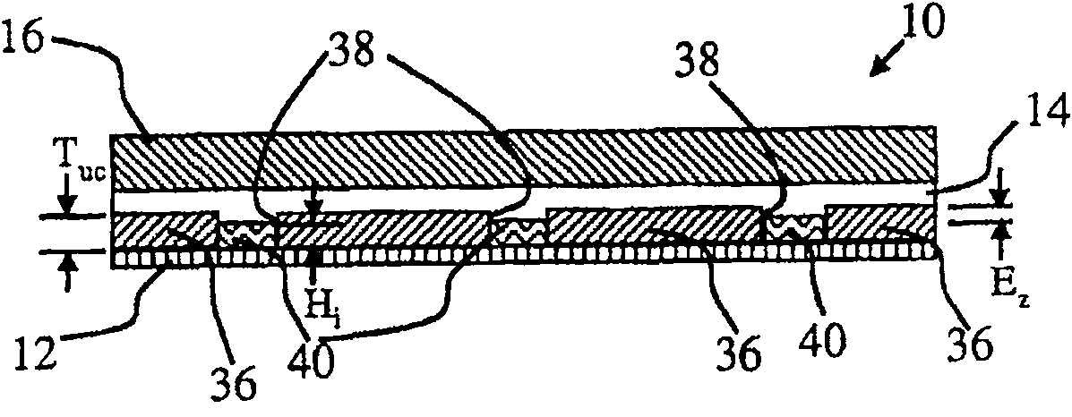
[0026] Referring to the drawings, like numerals refer to like components. figure 1 A side view of a torque transmitting device 10 according to one embodiment of the present invention is shown. Torque transmitting device 10 is commonly referred to in automotive applications as a clutch or brake. The device 10 has a first or friction plate 12 and a second or reaction plate 16 . Friction plate 12 is separated from reaction plate 16 by a layer of lubricating fluid 14 . A fluid lubricant 14 disposed between the reaction plate 16 and the friction plate 12 provides a lubricating layer between the plates. The torque transmitting device 10 is connected between the drive shaft 28 and the driven shaft 30 . More specifically, the friction plate 12 is coupled to the drive shaft 28 and the reaction plate 16 is coupled to the driven shaft 30 . Drive shaft 28 is typically coupled to a torque-generative device such as an internal combustion engine (not shown). The driven shaft 30 may be c...


PUM


Abstract

The clutch of the present invention has a reaction plate, a friction plate, a friction layer, at least one incompressible member, and a fluid lubricant. The friction plate is disposed adjacent the reaction plate to frictionally engage the reaction plate to transmit drive torque between the reaction plate and the friction plate upon application of a compressive force. The friction layer has at least one groove. The at least one incompressible member is disposed within the at least one groove to prevent further compression of the friction layer by the reaction plate. The at least one incompressible member is adhered to the friction plate, and a fluid lubricant is disposed between the reaction plate and the friction plate for providing a lubricating layer between the plates.

Description

[0001] This application claims priority to US Provisional Application No. 60 / 829,554, filed October 16,2006. The disclosures of the aforementioned applications are hereby incorporated by reference. technical field [0002] This invention relates to torque transmitting devices and to clutches or brakes for controlling the operation of mechanical devices such as transmissions or limited slip differentials. Background technique [0003] Torque transmitting devices such as clutches or brakes are commonly used in the automotive industry. For example, vehicle transmissions employ various clutches to engage and disengage gear sets of the transmission to provide forward or reverse gear ratios. [0004] Generally speaking, a clutch includes a friction plate and a reaction plate. The friction plate has a layer of friction material attached to the surface opposite the reaction plate. Traditional friction materials are (a) cellulose / Kevlar / resin based materials; (b) sintered metal fi...

Claims


Application Information

Patent Timeline
Patent Type & Authority Patents(China)
IPC IPC(8): F16D13/38F16D13/60F16D13/74F16D69/02
Inventor G·莫尔杜克霍维奇
Owner GM GLOBAL TECH OPERATIONS LLC
Learn More