Logic analyzer and its waveshape displaying method

A logic analyzer and waveform display technology, applied in the field of logic analyzers, can solve the problem that waveform data cannot correctly reflect waveform characteristics, etc.

Active Publication Date: 2009-11-04
SUZHOU RIGOL PRECISION ELECTRIC TECH
View PDF6 Cites 0 Cited by
  • Summary
  • Abstract
  • Description
  • Claims
  • Application Information

AI Technical Summary

Problems solved by technology

[0006] In order to solve the defect that the existing logic analyzer cannot correctly reflect the original waveform characteristics when displaying the compressed or enlarged waveform data, the purpose of the present invention is to provide a waveform display method of the logic analyzer and its logic analyzer

Method used


Image

  • Logic analyzer and its waveshape displaying method
  • Logic analyzer and its waveshape displaying method
  • Logic analyzer and its waveshape displaying method

Examples


Embodiment 1

[0031] This embodiment describes in detail the display of the logic analyzer in the running state. At this time, the logic analyzer needs to compress the data and display it while collecting the data.

[0032] Firstly, the logic analyzer stores the collected waveform data points in the storage device, and then fetches the waveform data points from the storage device for display. Generally, the number of stored waveform data points is larger than the row pixels of the screen. If all the stored waveform data points are to be displayed on the display at one time, these data points need to be compressed.

[0033] Firstly, the collected waveform data points are compressed into data points of screen row pixels. At this time, each compressed waveform data point is composed of multiple bits of the collected waveform data points. Then, for each compressed data point, all the bit phases are ORed to obtain a maximum value, and all the bit phases are ANDed to obtain a minimum value, and ...

Embodiment 2

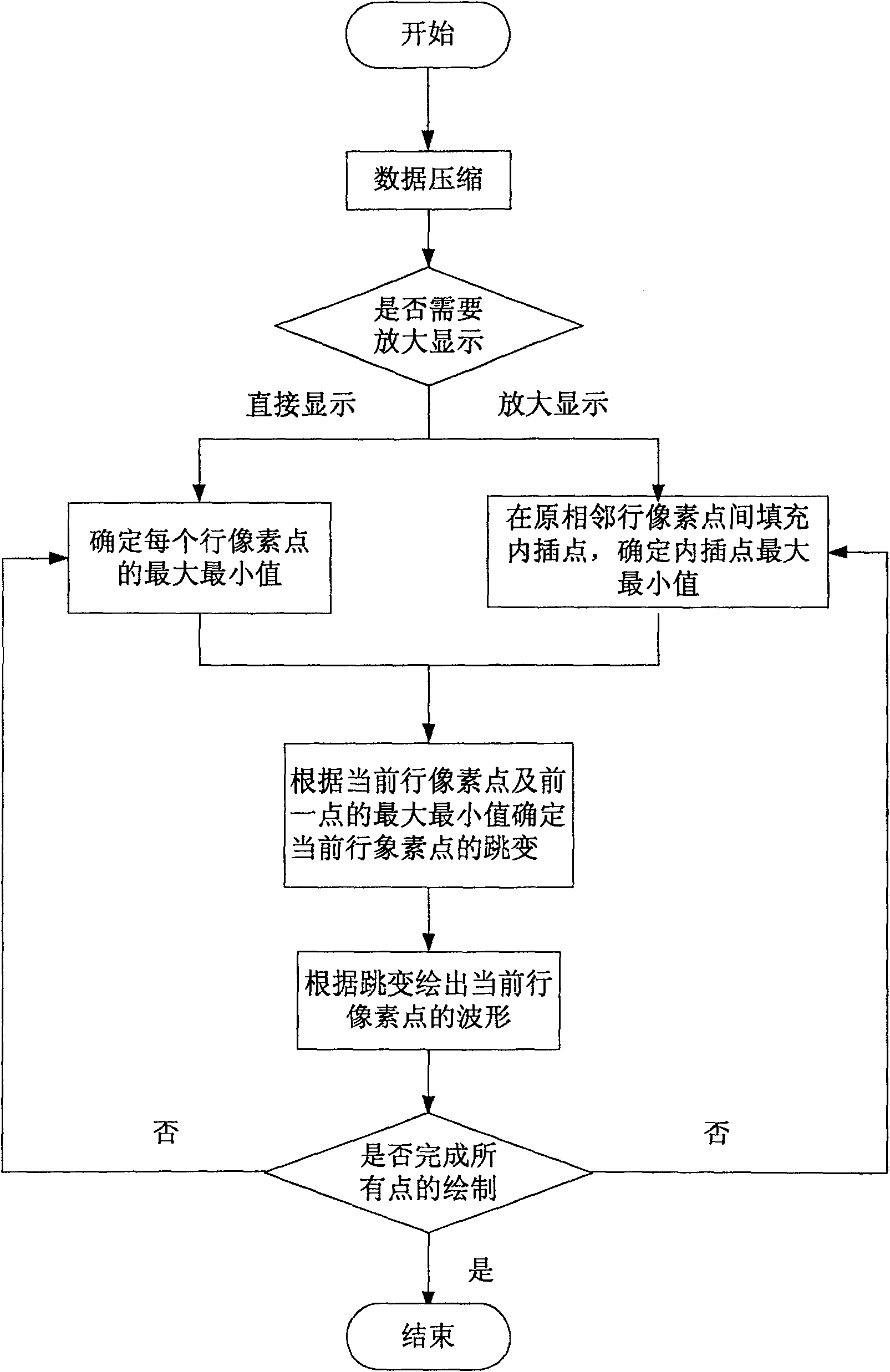
[0056] This embodiment describes in detail the situation that the logic analyzer needs to enlarge and display the compressed waveform. At this time, you can choose the amplification ratio by selecting the gear of the logic analyzer.

[0057] When the number of data points to be displayed is less than the number of screen row pixels, it is necessary to fill the interpolation points between the two row pixel points so that the waveform can be displayed continuously. The present invention provides an interpolation method, which uses the maximum and minimum values ​​of the previous point in adjacent rows of pixel points during compressed display as the maximum and minimum values ​​of the interpolation points to form multiple interpolation points. In this way, the maximum and minimum values ​​of pixels in each row after the enlargement are determined.

[0058] Like the compressed display method, it is also necessary to determine the display mode of the pixels in the current row ac...

Embodiment 3

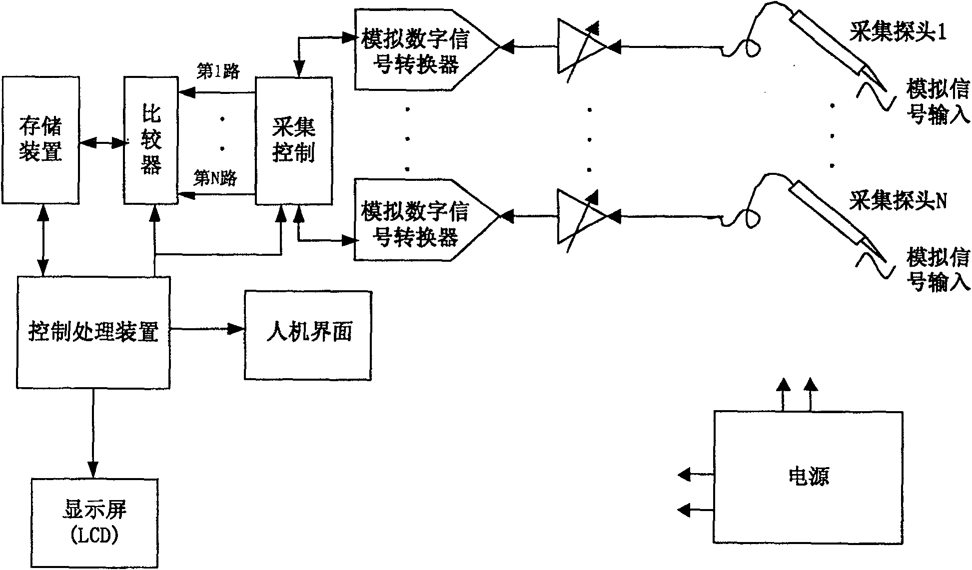
[0061] This embodiment is a logic analyzer. Figure 4 It is the structural diagram of the logic analyzer of this embodiment. As shown in the figure, the logic analyzer of the present invention adds a data scaling device and a display processing device on the basis of the existing logic analyzer, and they are respectively connected with the control processing device. The data scaling device is used to compress and display the collected waveform data points according to the control of the control processing device, or to enlarge and display the compressed points according to an external response instruction. The display processing device determines the display mode of each row of pixels according to the compressed or enlarged maximum and minimum values ​​of each row of pixels, and finally displays it on the screen.

[0062] Such as Figure 5 As shown, the data scaling device further includes a data reduction unit, a data amplification unit and an interpolation unit. The data r...


PUM


Abstract

A waveform display method of a logic analyzer, comprising: collecting and storing waveform data points; compressing the stored waveform data points into waveform data points twice as large as screen row pixels, calculating the maximum and minimum values ​​of the compressed waveform data points, and They correspond to the maximum and minimum values ​​of the pixels in the row, and determine the display mode of the pixels in the current row according to the maximum and minimum values ​​of the pixels in the current row and the previous point, and display the compressed waveform on each row of pixels; when received External response command, when the compressed line pixel waveform needs to be enlarged and displayed, interpolation points are filled between adjacent line pixel points, and the maximum and minimum values ​​of the previous point of the adjacent line pixel points are used as interpolation The maximum and minimum values ​​of the points, the display mode of the enlarged current row of pixels is determined according to the enlarged current row of pixels and the maximum and minimum values ​​of the previous point, and each row of pixels after the enlargement is displayed according to the display method on the waveform.

Description

technical field [0001] The invention relates to the field of logic analyzers, in particular to a waveform display algorithm of the logic analyzer and the logic analyzer. Background technique [0002] A logic analyzer is an instrument that collects and displays digital signals from test equipment using a clock. Since a logic analyzer is primarily used for testing, it does not have as many voltage levels as an oscilloscope does, but typically only displays two voltages (logic 1 and logic 0). Therefore, after setting the reference voltage, the logic analyzer judges the number to be tested through the comparator. The one higher than the reference voltage is logic 1, and the one lower than the reference voltage is logic 0. By judging the level of the voltage, a digital waveform is formed. , according to the digital waveform, you can find where the abnormality occurs. In addition, because the logic analyzer does not display the actual waveform of the signal, compared with the ge...

Claims


Application Information

Patent Timeline
Patent Type & Authority Patents(China)
IPC IPC(8): G01R31/3177G01R31/317
Inventor 王悦王铁军李维森
Owner SUZHOU RIGOL PRECISION ELECTRIC TECH
Why Eureka
Try Eureka