Supercharge Your Innovation With Domain-Expert AI Agents!

Multi-load topology cabling architecture

A printed circuit board and topology technology, applied in the direction of printed circuits, printed circuits, printed circuit components, etc., can solve the problems of large difference in transmission line length, affecting signal integrity, non-monotonic receiving end, etc., to improve transmission quality, Reduce the effect of non-monotonic phenomena

Inactive Publication Date: 2009-11-18
HONG FU JIN PRECISION IND (SHENZHEN) CO LTD +1
View PDF6 Cites 0 Cited by
  • Summary
  • Abstract
  • Description
  • Claims
  • Application Information

AI Technical Summary

Problems solved by technology

However, in the actual design, due to the limitation of the location of the chip at the receiving end, the length of each transmission line is quite different. figure 1 The receiving end 70 is farther away from the signal transmitting end 100 than the receiving ends 60, 80, and 90. At this time, the receiving end 70 will reflect the high-frequency transient signal to the receiving ends 60, 80, and 90, and at the receiving ends 60, 80, and 90 Produces non-monotonic phenomena that affect signal integrity and lead to timing and digital operation errors
Please refer to figure 2 , is the waveform diagram on the receiving end of the multi-load wiring architecture of the existing printed circuit board, in which the signal curves 66, 77, 88, and 99 correspond to the signal simulation curves of the receiving end 60, 70, 80, and 90, we can see The signal simulation curves 66, 88, 99 corresponding to the receiving ends 60, 80, 90 have serious non-monotonic phenomena during the rising period, resulting in timing and digital operation errors

Method used


Image

  • Multi-load topology cabling architecture
  • Multi-load topology cabling architecture
  • Multi-load topology cabling architecture

Examples


Embodiment Construction

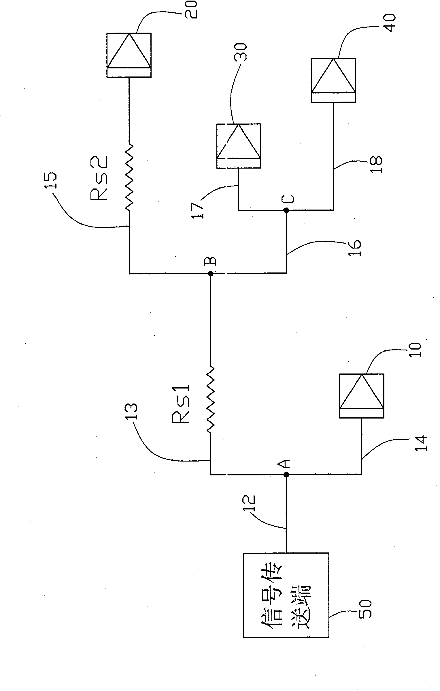
[0012] Please refer to image 3 , is a schematic diagram of a preferred embodiment of the wiring structure of a printed circuit board with multiple load topological wiring structures of the present invention. In the printed circuit board, a signal transmission terminal 50 is connected to a first connection point A via a main transmission line 12, and the first connection point A is connected to a second connection point via two branch transmission lines 13 and 14 respectively. B and a first signal receiving end 10, the second connection point B is connected to a second signal receiving end 20 and a third connection point C via two branch transmission lines 15, 16 respectively, the third connection point C is then respectively connected to a third signal receiving end 30 and a fourth signal receiving end 40 via two branch transmission lines 17, 18, wherein the distance between the second signal receiving end 20 and the signal transmitting end 50 is shorter than that of the seco...


PUM


Abstract

A multiple load topological wiring structure applies to wiring of multiple signal receiving ends for the same signal transmitting end on a printed circuit board. The signal transmitting end is connected to a first connection point via a main transmission line; the first connection point is connected to a second connection point and a first signal receiving end respectively via two branch transmission lines; the second connection point is connected to a second signal receiving end and a third signal receiving end respectively via two branch transmission lines; the distance between the second signal receiving end and the signal transmitting end is larger than the distance between the first and the third signal receiving ends and the signal transmitting end; a damping resistor is connected in series on the transmission line between the second connection point and the second signal receiving end.

Description

technical field [0001] The invention relates to a printed circuit board, in particular to a printed circuit board with multiple load topological wiring structures. Background technique [0002] On the printed circuit board, due to the limitation of the component placement space, there is a huge gap in the distribution of multiple loads on the same transmission end and the receiving end. Due to the unbalanced distribution of the distance between the loads on the computer motherboard, some high-frequency transients are caused. The signal is reflected from the farthest receiver to other closer receivers. At this time, a non-monotonic phenomenon (non-monotonic) will occur in the signal of the receiver closer to the load. This phenomenon will affect the signal integrity, resulting in timing and digital operations. mistake. [0003] For the line wiring of multiple loads, the existing method is to connect a resistor in series close to the signal transmission end to match the outpu...

Claims


Application Information

Patent Timeline
Patent Type & Authority Patents(China)
IPC IPC(8): G06F17/50
CPCH05K2201/10022H05K2201/09254H05K1/0237H05K1/0246
Inventor 许寿国白家南杜晓荃
Owner HONG FU JIN PRECISION IND (SHENZHEN) CO LTD
Features
  • R&D
  • Intellectual Property
  • Life Sciences
  • Materials
  • Tech Scout
  • Unparalleled Data Quality
  • Higher Quality Content
  • 60% Fewer Hallucinations
Learn More