
Gardening current connector structure

A connector and water flow technology, applied in the direction of couplings, mechanical equipment, etc., can solve the problems of unsmooth push and pull, increase material cost and processing cost, reduce service life, etc., to improve economic benefits, omit assembly and cost, Avoid the effects of elastic fatigue

Inactive Publication Date: 2009-12-02
YUAN MEI CORP
View PDF5 Cites 0 Cited by
  • Summary
  • Abstract
  • Description
  • Claims
  • Application Information

AI Technical Summary

Problems solved by technology

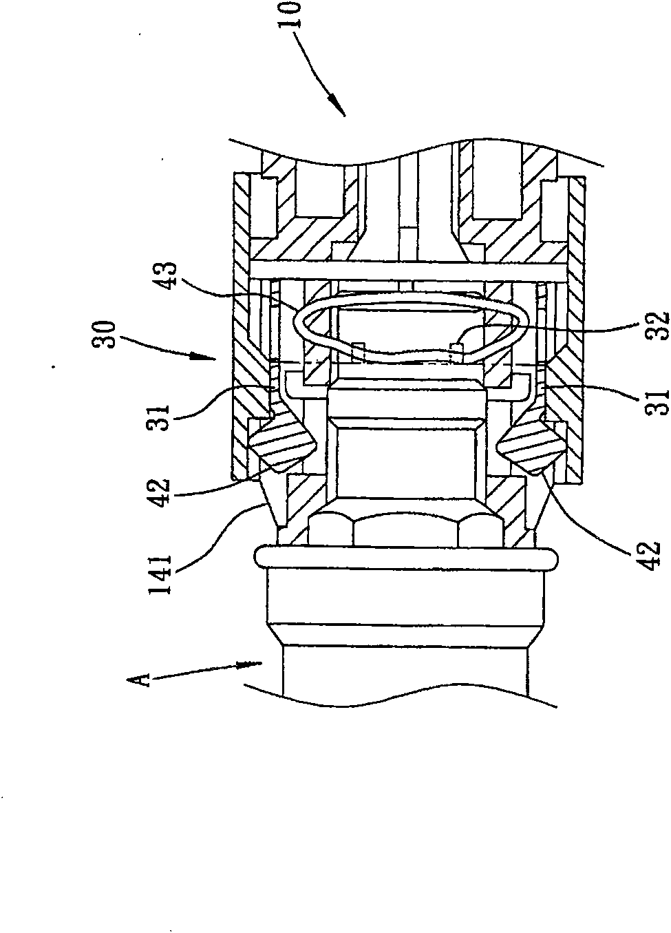
[0003] The above-mentioned known structure still has the following deficiencies: 1. The elastic body 43 of the elastic locking part 40 is arc-shaped, so when the user wants to push the sleeve 30, it is easy to cause elasticity due to pressure. Body 43 twists and deforms (as figure 2 As shown), the elastic function is reduced and the resisting function of the protrusion 31 disappears, thereby reducing the service life; 2. The elastic body 43 of the elastic locking member 40 is arc-shaped, so when the user wants to press the sleeve 30 , it is easy to cause the locking body 42 to get stuck due to the uneven force point, resulting in unsmooth push and pull and jamming, resulting in inconvenience in use; 3. The sleeve 30 can be detached from the mouthpiece A only by pressing down The catch body 42 is snapped and taken out, so once the sprinkling process is inadvertently pushed to the sleeve 30, causing the joint A to be impacted by the water pressure and instantly loosened, it will be splashed and wet by the water flow, making it more inconvenient to use
[0004] In addition, the water flow connector of US Patent No. US7021669 is assembled on the main body with a number of locking bodies and springs, so that the required components are numerous and complicated, which makes assembly time-consuming and inconvenient, and relatively increases the material cost and processing cost. Economic benefits and market competitiveness

Method used


Image

  • Gardening current connector structure
  • Gardening current connector structure
  • Gardening current connector structure

Examples


Embodiment Construction

[0064] The preferred embodiment of the present invention is described in detail below in conjunction with accompanying drawings:

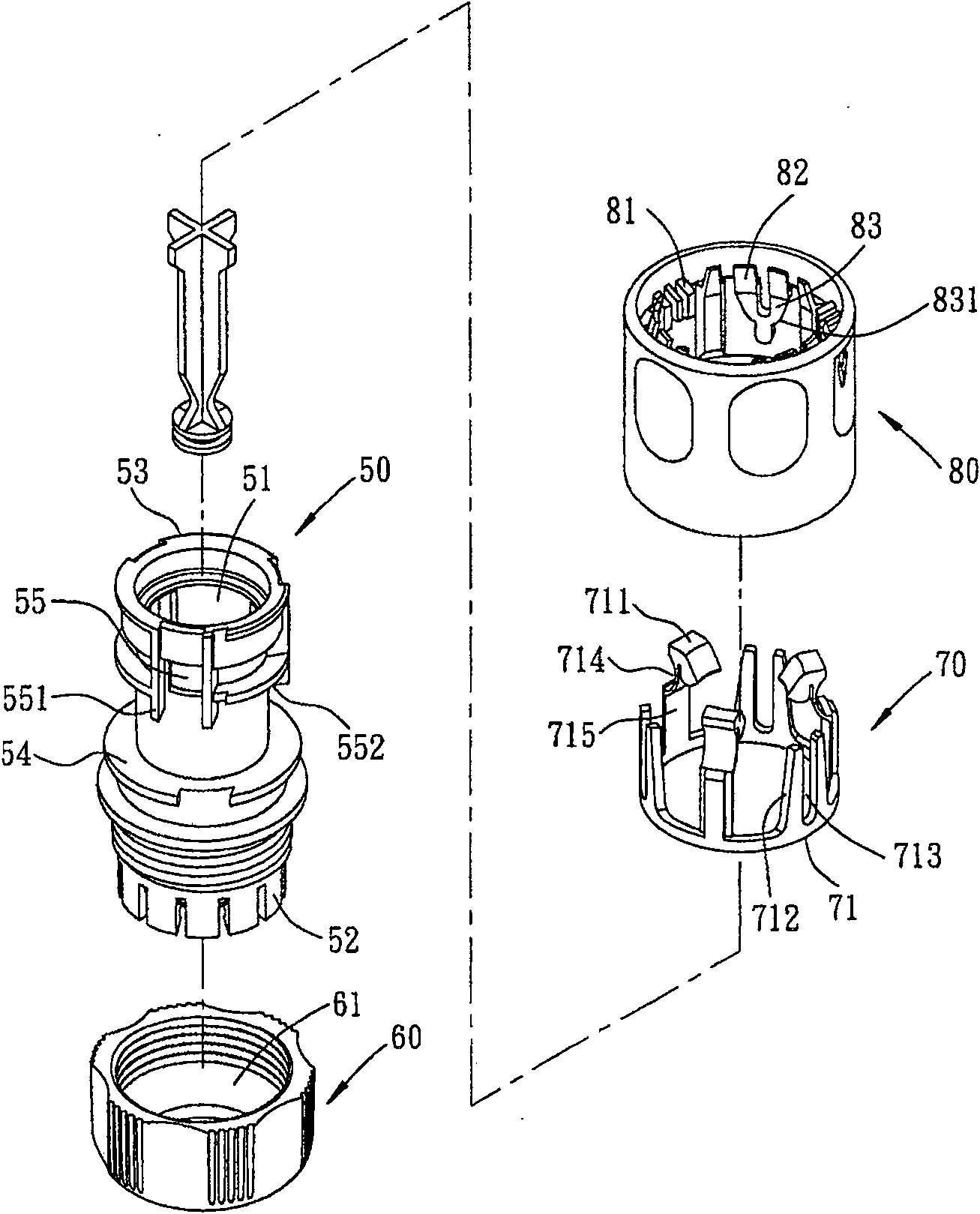
[0065] Such as image 3 Shown, is the three-dimensional exploded view of the present invention (please also refer to Figure 4 ), which includes: a body 50, a lock sleeve 60, an elastic latch 70 and a sleeve 80, wherein the body 50 is in a penetrating shape so that a water guide 51 is formed inside, and an external thread section is set at the end of the body 50 and the ring is provided with a plurality of The pressing tooth 52 is matched with a locking sleeve 60 with a push-out surface 61 inside to clamp the water pipe. A number of anti-reverse blocks 53 are arranged on the top of the ring outward, and a seat 54 is arranged in the middle, and a ring is arranged on the top of the seat 54. Several slots 55, and the two sides of the slots 55 are protrudingly provided with limiting blocks 551, and an abutting portion 552 is arranged between two limit...


PUM


Abstract

The invention relates to a current connector structure used for gardening. The current connector structure is formed by assembling a body, elastic clamping pieces and a sleeve, wherein, the body is provided with a plurality of slotted holes which are respectively used for clamping of a clamping piece; the elastic clamping pieces are annularly provided with a plurality of pairwise elastic feet to respectively form an elastic space; the inner wall of the sleeve is annularly provided with a plurality of pushing blocks which are just opposite to the two elastic feet; when the pushing blocks of the sleeve are pressed down, the elastic feet can relatively form a clamping elastic force, and then the sleeve can be quickly lifted elastically and reset, thereby the phenomena of distortion and clamping of an elastic body of the prior connector when the sleeve is pressed down and elastic fatigue can be avoided in the aspect of operation which is made to be smooth and easy.

Description

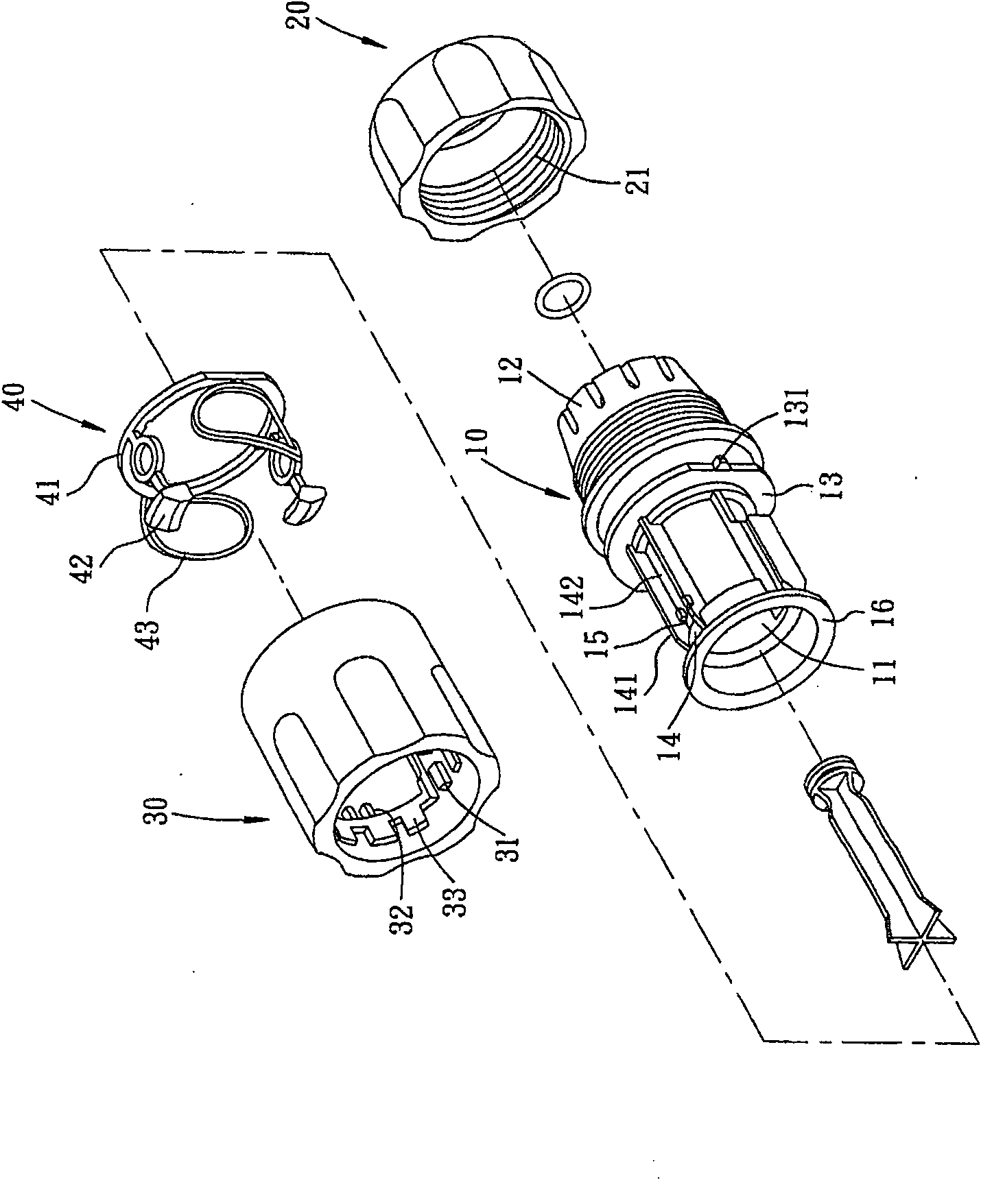
technical field [0001] The invention relates to a connector structure, in particular to a gardening water flow connector structure. Background technique [0002] Such as figure 1 As shown, it is the three-dimensional exploded view of Taiwan New Patent Announcement No. 260238 (please also refer to figure 2 ), which includes: a body 10, a lock sleeve 20, a sleeve 30 and an elastic latch 40, wherein the body 10 is in a through shape, and a sleeve 11 is provided inside the body 10, and one end of the sleeve 11 is connected to The inner walls of the main body 10 are connected to form a flange. The other end of the sleeve 11 extends outward to the end of the main body 10, and the end is provided with a plurality of cogs 12, and a seat 13 is provided in the middle, and a seat 13 is further provided on the seat 13. There is a directional flange 131, and a plurality of guide grooves 14 are arranged at equal intervals on the front end of the body 10. Guards 141, 142 are formed on b...

Claims


Application Information

Patent Timeline
Patent Type & Authority Patents(China)
IPC IPC(8): F16L37/084
Inventor 王金垣罗顺南
Owner YUAN MEI CORP
Learn More