Discharge device of injection moulding machine in two-stage type

An injection molding machine, two-stage technology, applied in the discharge device field of the residual plastic of the two-stage injection molding machine, can solve the problems of polluting the quality of the finished product, polluting the finished product, unable to rotate, etc., and prolong the service life , Avoid the effect of deteriorating plastics from polluting the quality of finished products

Inactive Publication Date: 2010-01-20
IND TECH RES INST
View PDF4 Cites 0 Cited by
  • Summary
  • Abstract
  • Description
  • Claims
  • Application Information

AI Technical Summary

Problems solved by technology

[0005] However, for this type of two-stage injection molding machine, when it is actually running, due to the relative movement between the non-return shafts 61, 71 and the non-return shaft seats 60, 70, the matching clearance is also likely to cause melting. Glue overflow and leakage
In order to solve this problem in the prior art, the gap between the non-return shafts 61, 71 and the non-return shaft seats 60, 70 is designed to be reduced (the tolerance is reduced), or other leak-proof devices are added to prevent overflow; And during the measurement process, the high-pressure melt glue easily penetrates into the gap, so if the gap is too small, it may cause the non-reverse shafts 61 and 71 to be stuck and unable to rotate; moreover, for plastics with added fibers or powders, when these materials When it penetrates into the gap and cannot be discharged, it will be charred and cracked due to excessive heating. If it is mixed into the melt at this time, it will seriously pollute the quality of the finished product (especially the transparent injection product).
[0006] Therefore, how to invent a new type of discharge device that can be used in two-stage injection machines to solve the problems of non-reverse shaft stuck and deteriorated plastics polluting finished products has indeed become an urgent subject to be solved in related research and development fields.

Method used


Image

  • Discharge device of injection moulding machine in two-stage type
  • Discharge device of injection moulding machine in two-stage type
  • Discharge device of injection moulding machine in two-stage type

Examples


Embodiment 1

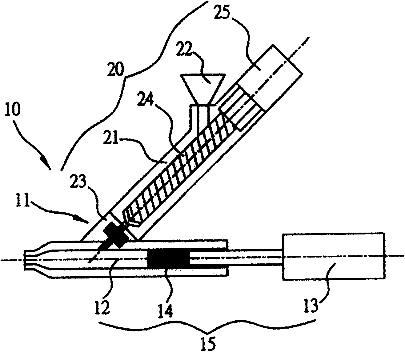
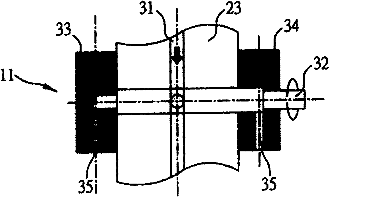
[0028] Figure 1A , Figure 1B This is embodiment 1 of the discharge device 11 of the two-stage injection molding machine 10 disclosed in the present invention, wherein the two-stage injection molding machine 10 is as Figure 1A , It includes an injection part 15 with an injection tube 12, a driving unit 13 and an injection rod 14, and a feeding part 20 obliquely arranged on the injection part 15 at an angle, and the feeding part 20 feeds the In the injection tube 12 of the injection part 15, the injection rod 14 is pushed by the driving unit 13, such as a driver, to perform plastic injection and complete injection molding; at the same time, the metering feeding part 20 is as shown in the figure, including materials Tube 21, hopper 22, check unit 23 (check shaft seat), feed screw 24, and feed drive motor 25. The feed drive motor 25 drives the feed screw 24 for feeding measurement. In addition, Other feeding parts that can achieve the same melt metering effect can also be used, s...

Embodiment 2

[0033] In addition to the content described in the above embodiment 1, the present invention can also be provided with an adjustable unit in the discharge holes 35 on the cover plates 33, 34 to adjust the discharge speed of the residual plastic according to the characteristics of different plastics; Therefore, with the adjustable unit, the non-return shaft 32 does not need to be replaced when the plastic is changed. It is only necessary to adjust the adjustable unit to change the flow rate of the residual plastic according to the fluidity of the changed plastic.

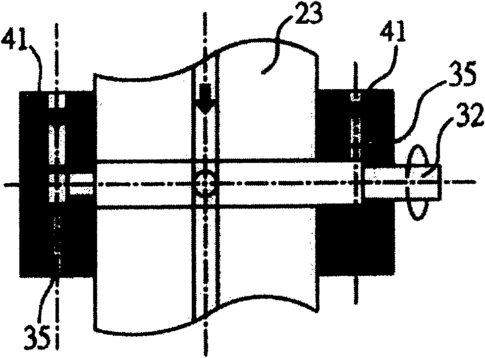
[0034] figure 2 It is the second embodiment of the present invention. It is provided with an adjusting bolt 41 in the first and second cover plates 33 and 34 respectively, and the adjusting bolt 41 is used to adjust the size of the discharge hole 35, thereby adjusting the residual plastic Discharge speed; therefore, when feeding or stopping feeding, the size of the discharging hole 35 can be adjusted according to the ch...

Embodiment 3

[0036] image 3 This is the third embodiment of the present invention, which is to modify the design of the adjustable unit, where the adjustable unit is a combination of the adjusting bolt 42, the adjusting spring 43 and the anti-leak block 44 for feeding or stopping When using the adjusting bolt 42 to adjust the pressure applied to the discharge hole 35 by the spring 43 and the anti-leak block 44 according to different plastic characteristics to determine the degree of leakage, thereby preventing the non-return shaft 32 from jamming and residual plastic burnt Disadvantages of cracking and polluting the melt.


PUM


Abstract

The present invention relates to a material discharge device of two-stage type injection-moulding machine. Said material discharge device includes the following several portions: non-return shaft seat with flow passage, it is placed between material-feeding portion and injection portion of said two-stage type injection-moulding machine for making the plastics in the material-feeding portion be fed into said injection portion by means of said flow passage; at least a non-return shaft placed in the non-return shaft seat, it can be used for closing flow passage and stopping plastics supply according to requirements; at least a cover plate set on one side of said non-return shaft seat, on said cover plate at least one material discharge hole is cut, said material discharge hole can be used for discharging out residual plastics between said non-return shaft seat and non-return shaft; and an adjustable unit for regulating discharging speed of said residual plastics.

Description

Technical field [0001] The invention relates to a discharging device for a two-stage injection molding machine, in particular to a discharging device for discharging residual plastics of the two-stage injection molding machine. Background technique [0002] With the continuous improvement of the precision and quality requirements of injection molding, the use of two-stage injection molding machines has become increasingly widespread. This is because the two-stage injection molding machine is like Figure 5 As shown, it includes a feeding part 50 and an injection part 55, and the metering and anti-reverse functions of the feeding part 50 can exert the effect of precise metering, thereby improving the quality of injection molding. [0003] The injection action of the two-stage injection molding machine is based on Figure 5 The shown motor 56 drives the metering screw 57 to rotate, so that the plastic in the hopper 58 enters the material pipe 59 for mixing and melting, and after formin...

Claims


Application Information

Patent Timeline
Patent Type & Authority Patents(China)
IPC IPC(8): B29C45/17B29C45/84
Inventor 陈明祈邓明昌冯文宏
Owner IND TECH RES INST
Why Eureka
Try Eureka