
Dust collector for communication equipment

A technology of communication equipment and vacuum cleaners, applied in the direction of vacuum cleaners, cleaning equipment, mechanical equipment, etc.

Active Publication Date: 2007-07-18
ZTE CORP
View PDF0 Cites 9 Cited by
  • Summary
  • Abstract
  • Description
  • Claims
  • Application Information

AI Technical Summary

Problems solved by technology

Unfortunately, there is currently no method or device that can effectively remove dust while the communication equipment is working.

Method used


Image

  • Dust collector for communication equipment
  • Dust collector for communication equipment
  • Dust collector for communication equipment

Examples


Embodiment Construction

[0025] The present invention will be further described below in conjunction with accompanying drawing.

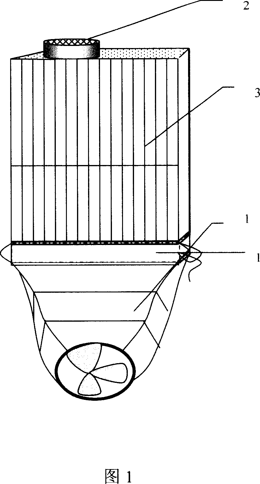
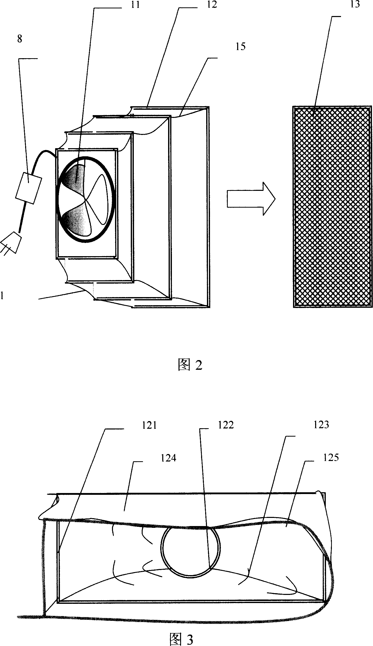
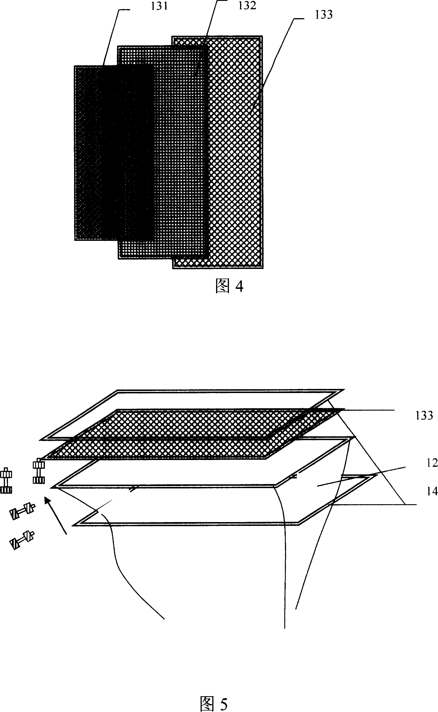
[0026] As shown in FIG. 1 , the dust remover for communication equipment of the present invention mainly includes two parts, which are respectively a vacuum cleaner 1 and a blower 2 . Such blowing and sucking forms a strong airflow channel inside the communication equipment. The blower 2 is placed at one end of the communication device 3 without fixed connection, while the vacuum cleaner 1 is docked at the other end of the communication device 3 and is fixed and sealed with the communication device 3. For example, a docking sleeve 124 ( As shown in Figure 3), one end of the docking sleeve is worn with a fixed tightening rope 125, and the fixed rope is used to tighten the 125 to firmly bolt the docking sleeve on the communication equipment, thus realizing the sealed docking of the vacuum cleaner and the communication equipment, the blower 2 and the vacuum cleaner 1 After co...


PUM


Abstract

A duster for communication equipment features that a blower and a cleaner are symmetrically arranged at opposite two sides of a communication equipment to be cleaned for blowing the dust out and then sucking it by cleaner.

Description

technical field [0001] The invention relates to a device for carrying out charged dust removal on communication equipment. Background technique [0002] Due to the long-term operation of communication equipment, a lot of dust will accumulate inside, which is very difficult to remove. According to the existing dust removal method, the equipment must be powered off first, and then the internal boards should be pulled out, so that cleaning can be carried out. But as we all know, communication equipment cannot be powered off at will, that is to say, communication equipment cannot be dusted at any time. Sometimes even the communication equipment has been in operation for several years without a dust removal, thus causing more and more dust inside the equipment. The dust inside the device fills the pin gaps of the IC chip, and some conductive carbon particles are mixed in it. These carbon particles with excellent conductivity pose a great threat to the IC chip. Once the time is...

Claims


Application Information

Patent Timeline
IPC IPC(8): B08B5/00F04D29/70A47L5/12
Inventor 周建明李明明
Owner ZTE CORP
Learn More