
Bipolar prick electric coagulation device

A technology of coagulator and burr, applied in the field of bipolar burr electric coagulator, can solve the problem of not fundamentally solving the problem of dust charging coagulation and dust removal efficiency, the number of charged particles coagulating less, and the electrostatic precipitator. Large volume and other problems, to achieve good coagulation effect, increase collision efficiency, and facilitate effective dust removal.

Inactive Publication Date: 2014-03-12
HEBEI UNIV OF TECH
View PDF13 Cites 12 Cited by
  • Summary
  • Abstract
  • Description
  • Claims
  • Application Information

AI Technical Summary

Problems solved by technology

[0004] Chinese patents with publication (report) numbers CN1390157A, CN1603004A, CN201168647X, CN201329312Y, CN202590955U, etc. respectively disclose the electrocoagulation method or equipment of the corresponding particles. The pre-charging devices of these smoke dust are usually realized by adding several deformation electric fields. , is essentially an extension of the electric field of electrostatic precipitator. It is to increase the electric field of dust removal in a disguised form to achieve the purpose of improving dust removal efficiency. It does not fundamentally solve the problem of dust charge coagulation and dust removal efficiency.
In addition, charging and coagulation are separated, and after the dust is charged, the use of post-positioned forced cross collisions will result in fewer coagulation times of charged particles, limited actual performance, or lack of charging intensity due to mechanism limitations. Insufficient force, it is difficult to achieve the expected cohesion performance

Method used


Image

  • Bipolar prick electric coagulation device

Examples


Embodiment 1

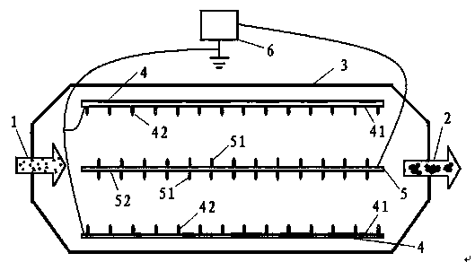
[0025] Design an electrocoagulator. The electrocoagulant is composed of a shell 3, two grounding plates 4 symmetrically arranged in the shell 3 and a high-voltage electrode 5, and the high-voltage electrode 5 is set on two grounding electrodes symmetrically up and down (of course, it can also be left and right). 4, and the different polar distances between the high-voltage pole plate 51 and the grounding pole plate 41 are equal; the grounding burrs 42 and the high-voltage thorns 52 are alternately arranged, and the high-voltage pole plate 51 is connected to the high-voltage pole of the high-voltage AC power supply 6, The two grounding plates 41 are both grounded; the electric field is supplied by the high-voltage AC power supply 6 .

[0026] The specific structural parameters of the electrocoagulator are designed as follows: the housing 3 is a cuboid, the air inlet 1 and the air outlet 2 are axially opened, the dimensions of the high-voltage pole plate 51 and the grounding pol...

Embodiment 2

[0029] The structural composition of the electrocoagulator is the same as in Embodiment 1.

[0030] The specific structural parameters of the electrocoagulator are designed as follows: the shell 3 is a cuboid, the air inlet 1 and the air outlet 2 are axially opened, the dimensions of the high-voltage electrode plate 51 and the ground electrode plate 41 are both 450×800mm, and the high-voltage electrode plate The equidistant distance between 51 and the grounding plate 41 is 150 mm, the length of the high-voltage thorns 51 is 20 mm, the length of the grounding burrs 41 is 10 mm, the diameters of the high-voltage burrs 52 and the grounding burrs 42 are 3.0 mm, and the high-voltage burrs The vertical and horizontal distances of the spines 52 are both 30 mm, the vertical and horizontal distances of the grounded spines 42 are both 30 mm, the rated output voltage of the high-voltage AC power supply 6 is 60 kV, and the frequency is 50 Hz.

[0031] According to the experiment, the wind...

Embodiment 3

[0033] The structural composition of the electrocoagulator is the same as in Embodiment 1.

[0034] The specific structural parameters of the electrocoagulator are designed as follows: the housing 3 is a cuboid, the air inlet 1 and the air outlet 2 are axially opened, the dimensions of the high-voltage electrode plate 51 and the ground electrode plate 41 are both 600×960mm, and the high-voltage electrode plate The equidistant distance between 51 and the grounding plate 41 is 100 mm, the length of the high-voltage thorns 51 is 15 mm, the length of the grounding burrs 41 is 8 mm, the diameters of the high-voltage burrs 52 and the grounding burrs 42 are 2.8 mm, and the high-voltage thorns 51 are 2.8 mm in diameter. The vertical and horizontal distances of the spines 52 are both 80 mm, the vertical and horizontal distances of the grounded spines 42 are both 100 mm, the rated output voltage of the high voltage AC power supply 6 is 120 kV, and the frequency is 120 Hz.

[0035] Accor...


PUM


Abstract

The invention discloses a bipolar prick electric coagulation device which is characterized in that the electric coagulation device mainly comprises a housing, a high-voltage electrode, two grounding electrodes and a high-voltage alternating current power supply, wherein the high-voltage electrode comprises a high-voltage polar plate and high-voltage pricks; the grounding electrodes comprise grounding polar plates and grounding pricks; the shapes and the structures of the two grounding electrodes are the same; pinpoints of the grounding pricks of the two grounding electrodes are opposite, and the two grounding electrodes are parallely arranged in two symmetrical edges of the housing; the high-voltage electrode is parallel to the two grounding electrodes, arranged with the two grounding electrodes in an equally spaced manner, and arranged between the two grounding electrodes; the pinpoints of the high-voltage pricks and the grounding pricks are in stagger arrangement relatively; the high-voltage polar plate is connected with the high-voltage alternating current power supply; the two grounding polar plates are both connected with the ground. The electric coagulation device can effectively coagulate fine dust particles in smoke, is convenient for a following electric precipitator to remove dust effectively, and has the characteristics of simple structure, small size, low cost, suitability for industrial popularization and application and the like.

Description

technical field [0001] The invention relates to flue gas dedusting technology, in particular to a bipolar prickly electric coagulator. The electric coagulation combiner can make the dust condense and then be purified and removed by the electrostatic precipitator. Background technique [0002] According to the latest research reports, my country has become one of the areas with the most serious fine particle pollution in the world. The country has begun to pay great attention to and started to deal with PM2.5 pollution. Because these fine dusts can directly enter the human respiratory system, and at the same time, these fine dusts are also the chief culprit of smog weather, which not only affects people's health, but also brings great inconvenience to people's daily life. As the main equipment for industrial dust collection, the electrostatic precipitator will surely become the entry point and key object of fine particle control. However, the traditional electrostatic prec...

Claims


Application Information

Patent Timeline
Patent Type & Authority Applications(China)
IPC IPC(8): B03C3/40B03C3/47B03C3/66
Inventor 黄超马秀琴孙优善王美艳张长平王晶
Owner HEBEI UNIV OF TECH
Learn More