Booster compressor

A compressor, booster technology, applied in mechanical equipment, machines/engines, liquid variable capacity machinery, etc., can solve problems such as poor performance

Inactive Publication Date: 2007-07-18
ANEST IWATA CORP
View PDF0 Cites 7 Cited by
  • Summary
  • Abstract
  • Description
  • Claims
  • Application Information

AI Technical Summary

Problems solved by technology

[0008] Continuously changing directions of excessive force on each sliding and rotating part produce wear and early failure resulting in poor performance over time

Method used


Image

  • Booster compressor
  • Booster compressor
  • Booster compressor

Examples


no. 1 approach

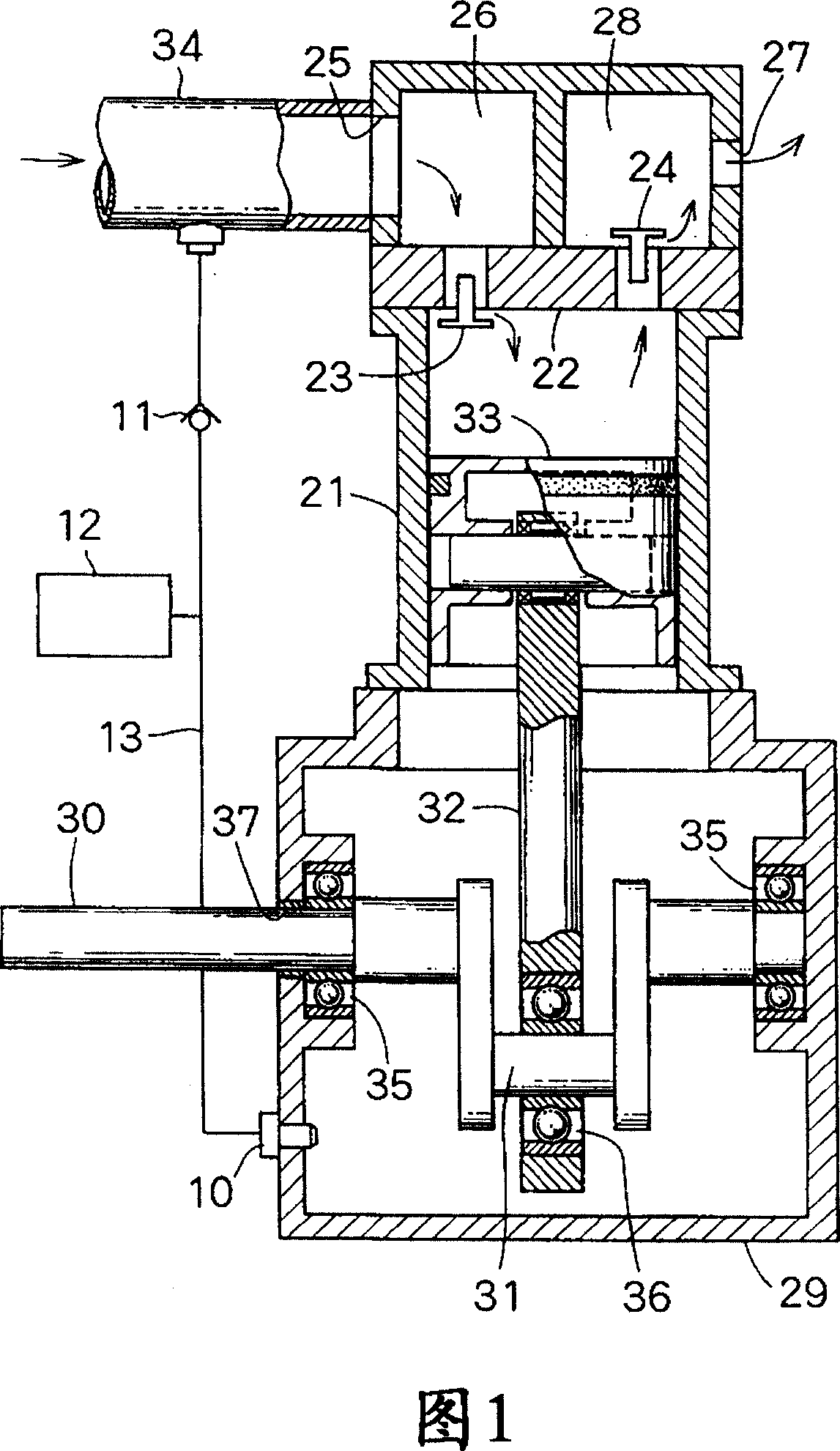
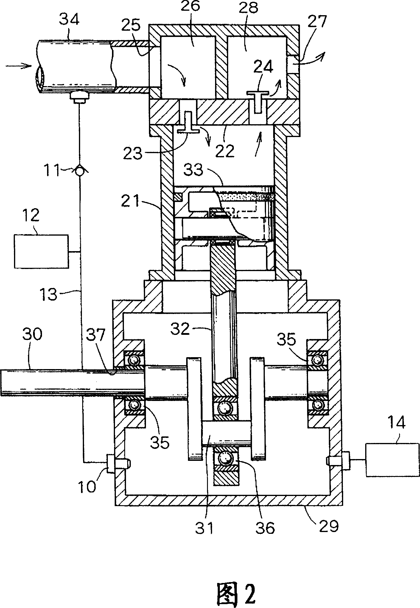
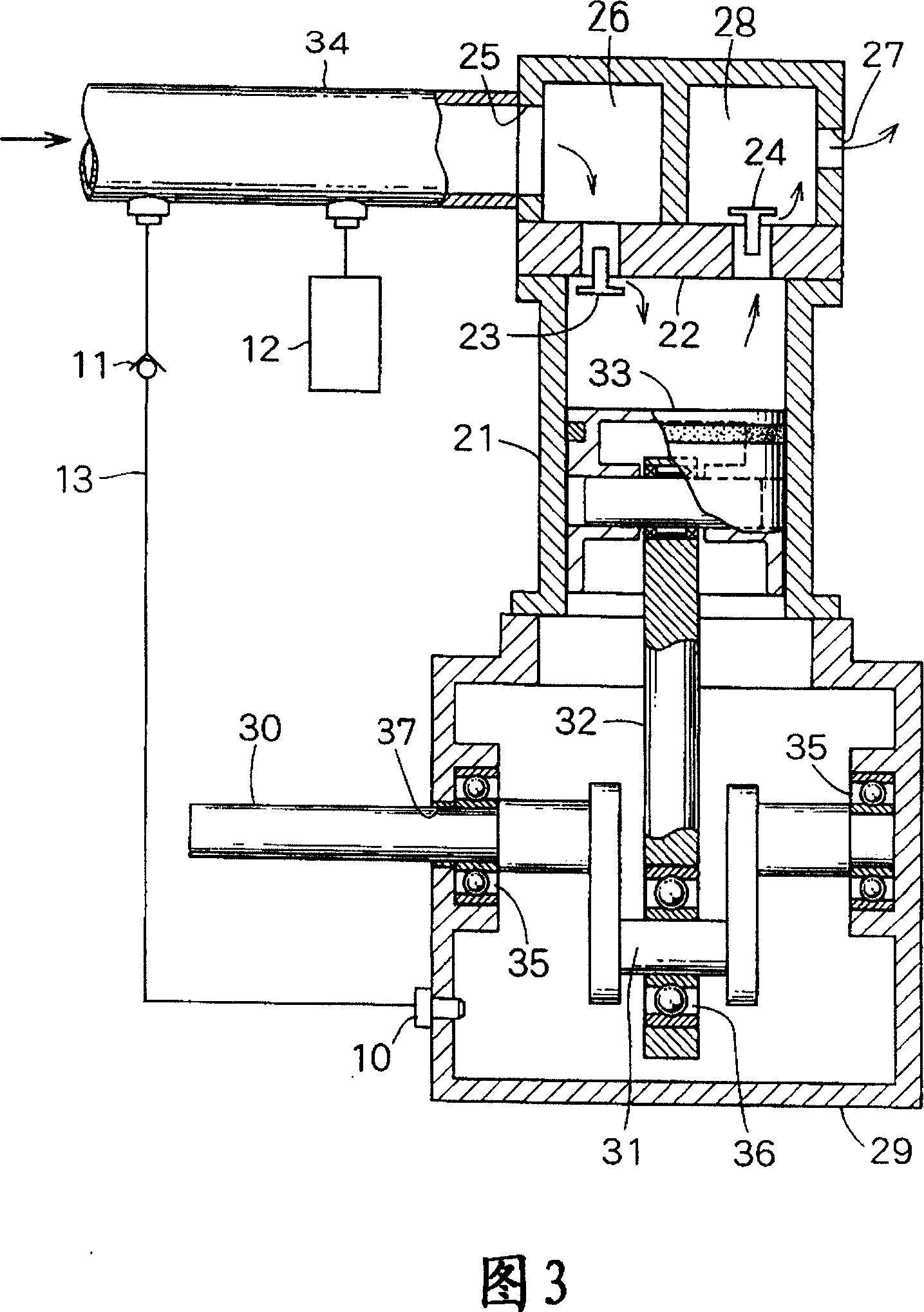
[0016] The basic structure of the booster compressor is not much different from that in Figure 4. The same reference numerals refer to the same elements as in FIG. 4 and descriptions thereof are omitted. Only the differences will be described below.

[0017] In FIG. 1 , the air holes 39 of FIG. 4 are absent. Instead, a compressed gas inlet 10 is formed. The compressed gas flow path 34 is connected to the compressed gas inlet 10 by a bypass pipe 13 comprising a check valve 11 and a pressure regulator 12 such as a pressure regulating valve or a pressure reducing valve, the check valve 11 facing the compressed gas flow path 34 closes and opens in the opposite direction.

[0018] When the compressed gas is supplied to the suction chamber 26 by opening a valve (not shown), the compressed gas is supplied to the crank case 29 through the bypass pipe 13 including the check valve 11 and the pressure regulator 12 and the compressed gas inlet 10, thereby The interior of the crankcase...


PUM


Abstract

A booster-type gas compressor comprises a compressed-gas flow path, a cylinder, and a piston that moves up and down in the cylinder to further compress a compressed gas fed into the cylinder from the compressed-gas flow path. In a crank case, a crank shaft is rotated with a driving shaft to move the piston up and down. The compressed-gas flow path is connected to the crank case via a bypath conduit to make pressure difference above and under the piston reduced.

Description

technical field [0001] The present invention relates to a booster type compressor in which compressed gas is compressed by reciprocating a piston. Background technique [0002] As shown in FIG. 4, a booster type compressor is known, in which an intake valve 23 and an exhaust valve 24 are provided at one end and the other end of the upper wall 22 of the cylinder 21, respectively. Above the intake valve 23 and the exhaust valve 24, an intake chamber 26 having an inlet 25 and an exhaust chamber 28 having an outlet 27 are provided. The piston 33 is reciprocated in the cylinder 21 by the piston rod 32 , and N, for example, sucked from the compressed gas flow path 34 via the inlet 25 2 Compressed gas, such as gas, is introduced into a cavity on piston 33 , further compressed and exhausted through exhaust valve 24 and outlet 27 , where piston rod 32 is driven by an external power source through crankshaft 31 of drive shaft 30 . [0003] The drive shaft 30 is rotatably fixed throu...

Claims


Application Information

Patent Timeline
Patent Type & Authority Applications(China)
IPC IPC(8): F04B35/01
CPCF04B2205/18F04B37/12F04B49/00F04B39/128E06C7/44E06C7/46
Inventor 井上弘
Owner ANEST IWATA CORP
Why Eureka
Try Eureka