Trigger switch

A technology for triggering switches and disconnecting positions, applied in the direction of electric switches, electronic switches, emergency contact forms, etc., can solve the problem of fine-tuning of motor speed, etc., and achieve the effect of easy fine-tuning

Active Publication Date: 2018-10-23
SATORI SWITCH IND
View PDF13 Cites 0 Cited by
  • Summary
  • Abstract
  • Description
  • Claims
  • Application Information

AI Technical Summary

Problems solved by technology

However, since the rotation speed of the motor is controlled not by the displacement of the operation part but by the additi...

Method used


Image

  • Trigger switch
  • Trigger switch
  • Trigger switch

Examples


Embodiment Construction

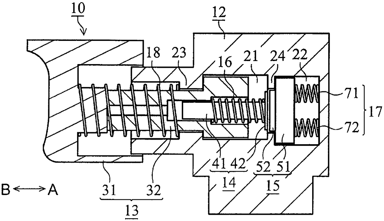
[0037] figure 1 The shown trigger switch 10 is used, for example, in an electric tool including a load such as a motor to adjust the electric power supplied to the load.

[0038] The trigger switch 10 includes a housing 12 . The frame body 12 has two accommodating spaces 21 , 22 and two partition walls 23 , 24 disposed inside. The partition wall 23 is arranged in the direction B of the storage space 21 and separates the storage space 21 from the outside. The partition wall 23 is provided with a through hole that communicates the storage space 21 with the outside. The partition wall 24 is arranged in the A direction of the storage space 21 and in the B direction of the storage space 22 , and partitions the two storage spaces 21 and 22 . The partition wall 24 is provided with a through hole that communicates the two storage spaces 21 and 22 .

[0039] The trigger switch 10 includes an operation unit 13 . The operation part 13 can be positioned relative to the frame body 12 ...


PUM


Abstract

It is enabled to facilitate fine adjustment of power as well as reduction of the amount of movement required to maximize the power. An actuator 13 is moved by operation of a user. A pressure sensitivesensor 15 detects applied pressing force. A pressing member 14 presses the pressure sensitive sensor 15. When the amount of movement of the actuator 13 is smaller than a predetermined amount, the pressing member 14 presses the pressure sensitive sensor 15 to apply force corresponding to the amount of movement of the actuator 13. When the amount of movement of the actuator 13 is not smaller than the predetermined amount, the pressing member 14 presses the pressure sensitive sensor 15 to apply force corresponding to pressing force applied to the actuator 13 by the user.

Description

technical field [0001] The present invention relates to trigger switches. Background technique [0002] Patent Document 1 discloses a variable speed switch that increases or decreases the amount of electric power supplied to a motor in accordance with the displacement of a switch operation portion. [0003] Patent Document 2 discloses a load gauge that detects a load applied to a load transmitting member with a strain receiving portion. [0004] prior art literature [0005] patent documents [0006] Patent Document 1: Japanese Patent Laid-Open No. 2012-252554 [0007] Patent Document 2: Japanese Patent Application Publication No. 39-23167 [0008] The variable speed switch disclosed in Patent Document 1 can maximize the rotation speed of the motor with a small displacement by converting the displacement of the switch operation part into a force pressing the load sensor by using an elastic body. However, since the amount of displacement of the switch operation part from...

Claims


Application Information

Patent Timeline
IPC IPC(8): H01H13/02H01H13/12H01H13/34
CPCH01H13/02H01H13/12H01H13/34H01H2207/048H01H2235/004H01H2239/024H01H2235/01H01H2227/028B25F5/00H01H9/06H01H13/08H03K17/9625H03K17/965H01H2231/048H02P7/00H02K11/24H02K11/28B23Q5/54H01H15/16H02K7/14H02P6/08
Inventor 樋川星
Owner SATORI SWITCH IND
Why Eureka
Try Eureka