Double-chamber ampoule

A container and flexible technology, applied in the field of double-chamber ampoules, can solve the problems of high manufacturing cost, too large, unusable container solutions, etc., and achieve the effect of rapid absorption

Inactive Publication Date: 2007-07-18
贝恩德·汉森
View PDF0 Cites 4 Cited by
  • Summary
  • Abstract
  • Description
  • Claims
  • Application Information

AI Technical Summary

Problems solved by technology

In known solutions, the material separation of the conveying medium in the dosing chamber from the propulsion medium in the container is achieved by means of a separating piston, so that no mixing occurs unintentionally, which would render this container concept unusable
Very low-viscosity conveying media can be discharged using the known container concept, but there is also the disadvantage that the partitioning of the piston in the known solution results in higher manufacturing costs and an excessively large size in the axial direction, especially in the conveying direction. constitute

Method used


Image

  • Double-chamber ampoule

Examples


Embodiment Construction

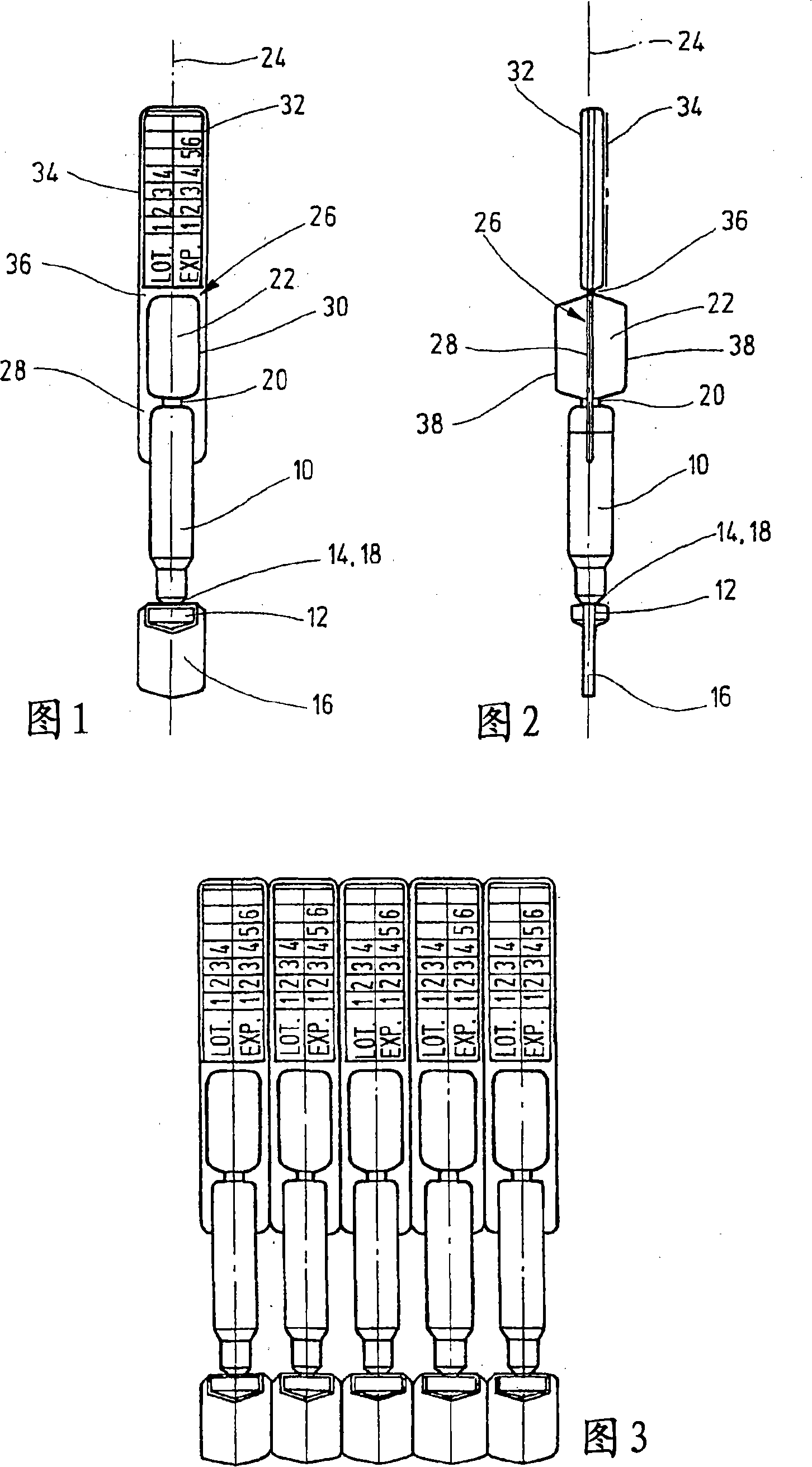
[0016] The container shown in the accompanying drawings consists of a transparent, elastic and flexible plastic, which can be manufactured, filled and non-woven by blow molding machines alone (see Figures 1 and 2) or together with other containers (see Figure 3). bacteria seal. The container has a tubular ingredient chamber 10, the lower end of which is seen in the figure closed by a twist closure (twist closure) 12, which has a constricted break slit 14 and a handle 16 for unscrewing the twist closure 12, to release the discharge opening 18 located at the lower end of the batching chamber 10. There is a conveying medium in the dosing chamber 10, for example a paste-like viscous medium such as eye ointment; the conveying medium preferably also includes a low-viscosity medium or even an aerosol, which can be discharged from the dosing chamber 10 during the spraying process Port 18 exits the container. The tubular structure of the ingredient chamber 10 facilitates insertion in...


PUM


Abstract

The invention relates to a receptacle comprised of an elastically flexible plastic material, comprising a dosing chamber (10), inside of which a medium to be discharged is located. One end of the dosing chamber (10) has a discharge opening (18), and the opposite end is connected via a junction point (20) to a compressible receptacle part (22) inside of which an, in particular, gaseous propelling medium is located. When compressing the receptacle part (22), the propelling medium forces, at least one part, the medium to be discharged out of the dosing chamber (10) via the discharge opening (18). An increased functional reliability in every application is ensured by virtue of the fact that the junction point (20) between the dosing chamber (10) and the receptacle part (22) is formed by a bottleneck provided for creating a capillary effect that, independent of the spatial position of the receptacle, prevents a transfer of the medium to be discharged from the dosing chamber (10) into the receptacle part (22) containing the propelling medium.

Description

technical field [0001] The invention relates to a container made of elastic and flexible plastic, comprising a dosing chamber in which a conveying medium is present, wherein one end of the dosing chamber has a discharge opening and the opposite end passes through a The connection part is connected to a compressible container part, in which an in particular gaseous propulsion medium is present, wherein when the container part is compressed, the propulsion medium at least partially pushes the transfer medium out of the dosing chamber via the discharge opening . Background technique [0002] Known from DE-PS 32 44 403 is a container of the same type made of elastic plastic material, which has a tubular dosing chamber in which an object medium is located, which is constructed such that the object The medium remains in the dosing chamber independently of the position of the container, which also has a compressible container part filled with a gaseous medium, whose volume is grea...

Claims


Application Information

Patent Timeline
Patent Type & Authority Applications(China)
IPC IPC(8): B65D1/09B65D83/00A61J1/06
CPCB65D1/095B65D83/00A61J1/06B65D1/09
Inventor 贝恩德·汉森
Owner 贝恩德·汉森
Why Eureka
Try Eureka