Hydraulically actuated impact apparatus

A drive and impact technology, used in mechanically driven excavators/dredgers, construction, earth movers/shovels, etc.

Inactive Publication Date: 2007-07-18
电力科技有限公司
View PDF2 Cites 5 Cited by
  • Summary
  • Abstract
  • Description
  • Claims
  • Application Information

AI Technical Summary

Problems solved by technology

This is a disadvantage when the arm of the machine carrying the bucket is fully extended as each tooth is attached to an independent pneumatic impact hammer, making the overall weight of the digging bucket much greater than conventional buckets

Method used


Image

  • Hydraulically actuated impact apparatus
  • Hydraulically actuated impact apparatus
  • Hydraulically actuated impact apparatus

Examples


Embodiment Construction

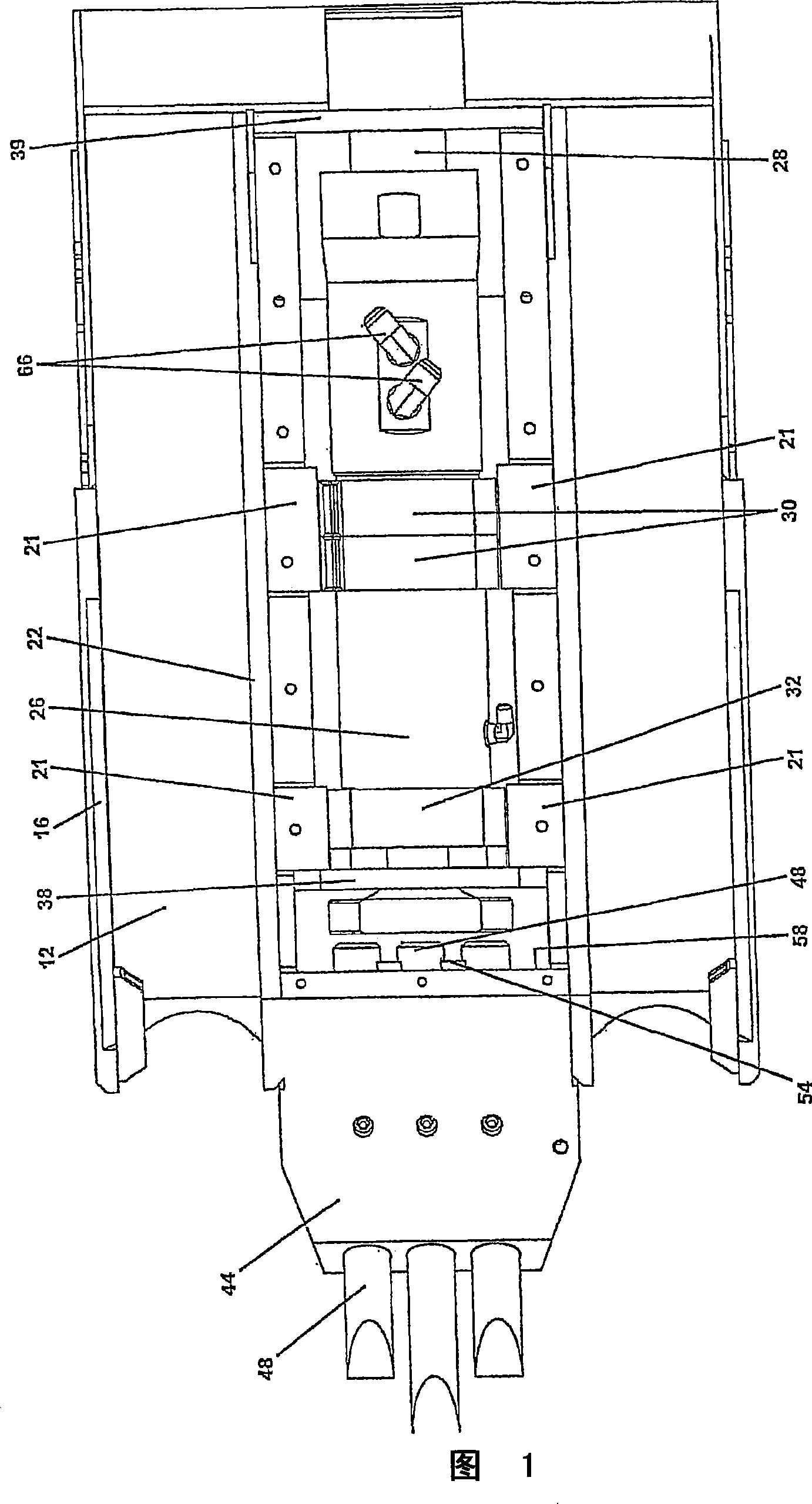
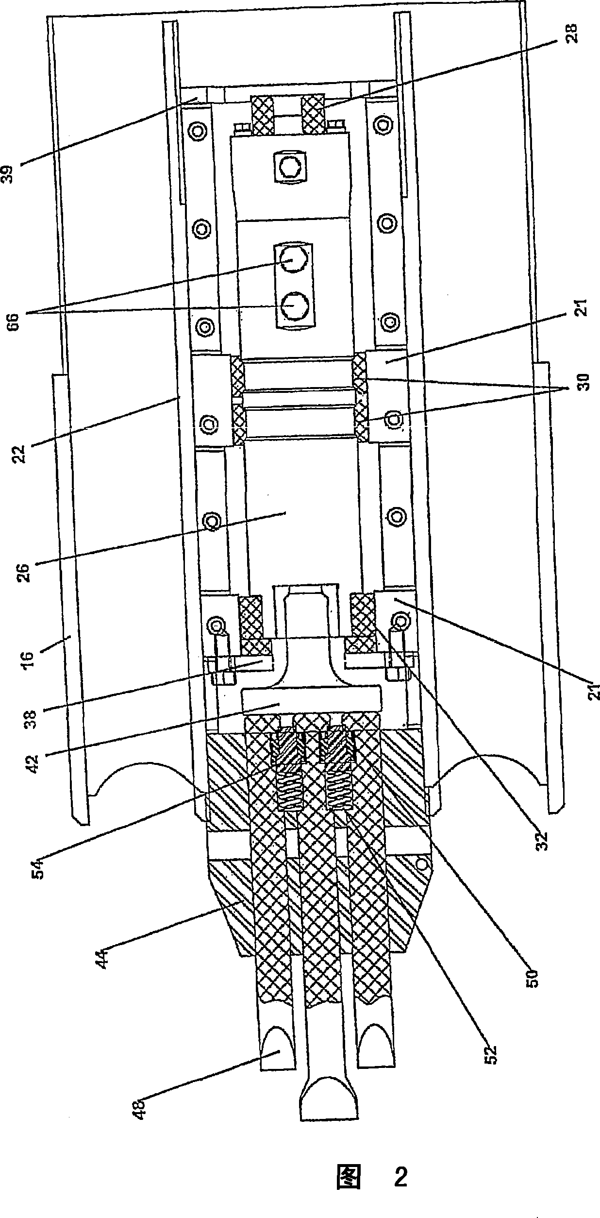
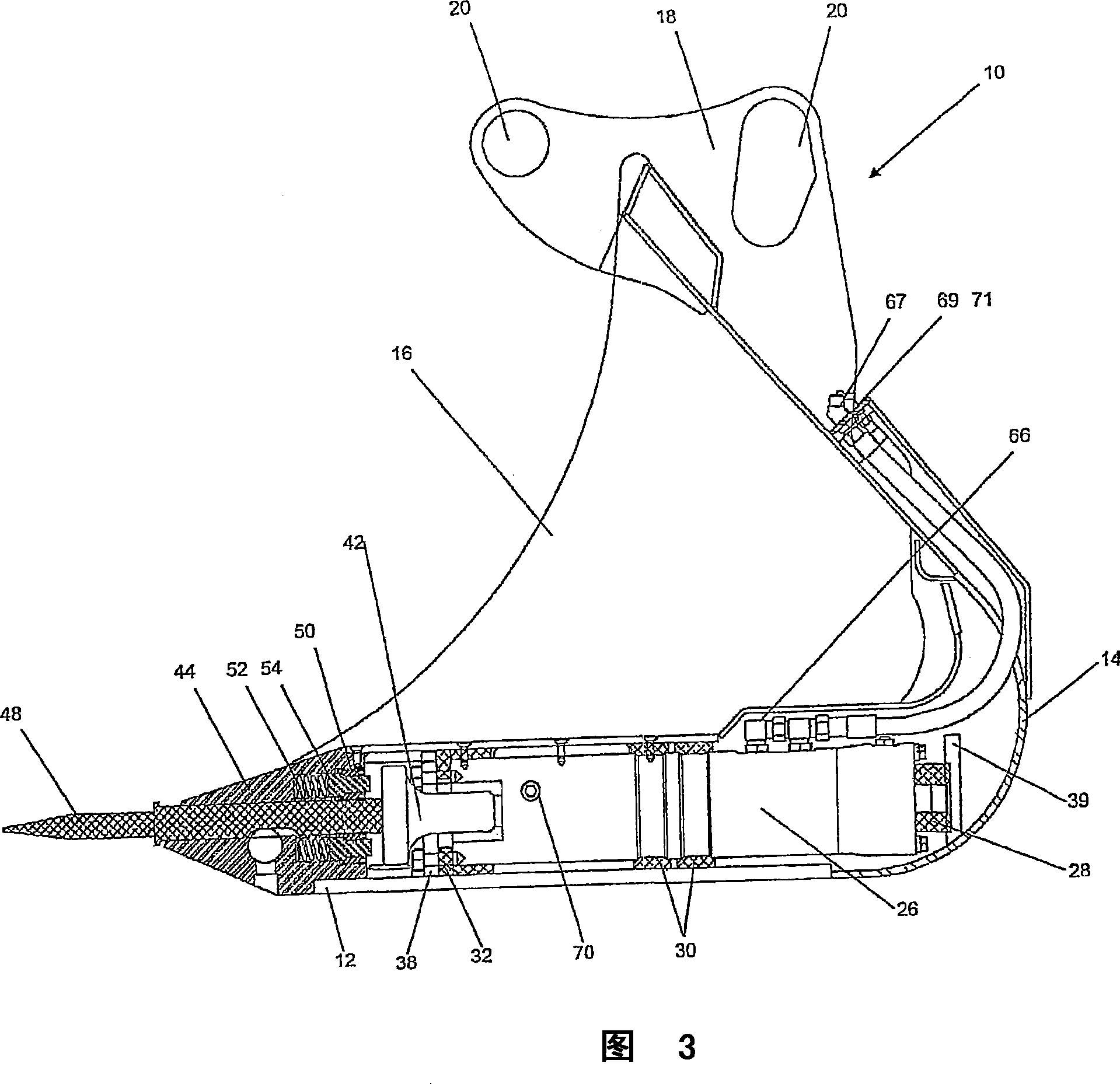
[0043] As mentioned in the Summary of the Invention, the present invention relates to an impact driver assembly. While the impact driver assembly may be used alone, in a preferred embodiment, the impact driver assembly 26 is preferably incorporated into a digging bucket.

[0044] Referring in more detail to the drawings and to the reference numerals therein, a preferred embodiment of the present invention is shown in FIGS. Dig in the bucket. In this regard, the bucket 10 is similar to US Patent No. 6,574,891.

[0045] The bucket 10 has a base 12, a rear wall 14, and side walls 16 with mounting brackets 18 having holes 20 in the upper surface for securing purposes.

[0046] Based on its purpose and its width, each bucket 10 is fitted with one or more impact drive assemblies 26 (for a multipurpose impact drive, see Figures 13-17). When used in series (more than one impact driver assembly per bucket 10), each impact driver assembly 26 is mounted side by side, separated by an i...


PUM


Abstract

An impact actuator assembly has a housing having a front, a rear, two opposite sides, a top and a bottom, and defining an actuator receiving area. A hydraulic actuator is fixedly mounted in the actuator receiving area, and provided with an actuator head, at least a portion of which extends forwardly of the actuator receiving area. A nosepiece is fixedly attached to the front of the housing at a distance from the actuator receiving area, defining a space between the nosepiece and the actuator head. The nosepiece is provided with at least one longitudinal hollow guide for receiving a tool pin, each of the tool pins having a rear and a front. The rear of the tool pin extends in the space between the nosepiece and the actuator head and the front of tool pin extends beyond the front of the housing. A plurality of hydraulic connectors are mounted on the housing and operatively connected to the actuator. When the actuator is actuated, the actuator head is engaged in reciprocating longitudinal movement to cyclically impact the tool pin.

Description

technical field [0001] The present invention relates to impact devices, and more particularly, to impact devices including impact driver assemblies. Background technique [0002] Digging buckets are well known in the art and are designed to dig hard soil and the like. One such digging bucket is described in US Patent No. 6,574,891, wherein the bucket includes a bucket body, a movable head, a movable base mounted between the movable head and an impact driver, the impact A type driver is disposed between and mounted on the bucket body and the movable head. [0003] Other arrangements have been described in the prior art, therefore reference is made to US Patent No. 4,625,438 which teaches an excavation bucket having a leading edge provided with a row of independent pneumatically driven excavating teeth. Each digging tooth is connected to an air hammer that reciprocates the tooth at high speed. This is a disadvantage when the arm of the machine carrying the bucket is fully e...

Claims


Application Information

Patent Timeline
Patent Type & Authority Applications(China)
IPC IPC(8): E02F3/40E02F3/00
CPCE02F3/405E02F3/966
Inventor P·盖农C·默里
Owner 电力科技有限公司
Why Eureka
Try Eureka