Supercharge Your Innovation With Domain-Expert AI Agents!

Vehicle controller for operating vechicle and its control method

一种控制器、车辆的技术,应用在制动器、电气控制、控制装置等方向,能够解决系统构造复杂等问题

Active Publication Date: 2007-07-25
DENSO CORP +1
View PDF2 Cites 2 Cited by
  • Summary
  • Abstract
  • Description
  • Claims
  • Application Information

AI Technical Summary

Problems solved by technology

Accordingly, when the vehicle controller is configured such that cruise control or the like is performed by performing vibration damping processing with respect to the cruise demand force, the system configuration becomes complicated

Method used


Image

  • Vehicle controller for operating vechicle and its control method
  • Vehicle controller for operating vechicle and its control method
  • Vehicle controller for operating vechicle and its control method

Examples


no. 1 example

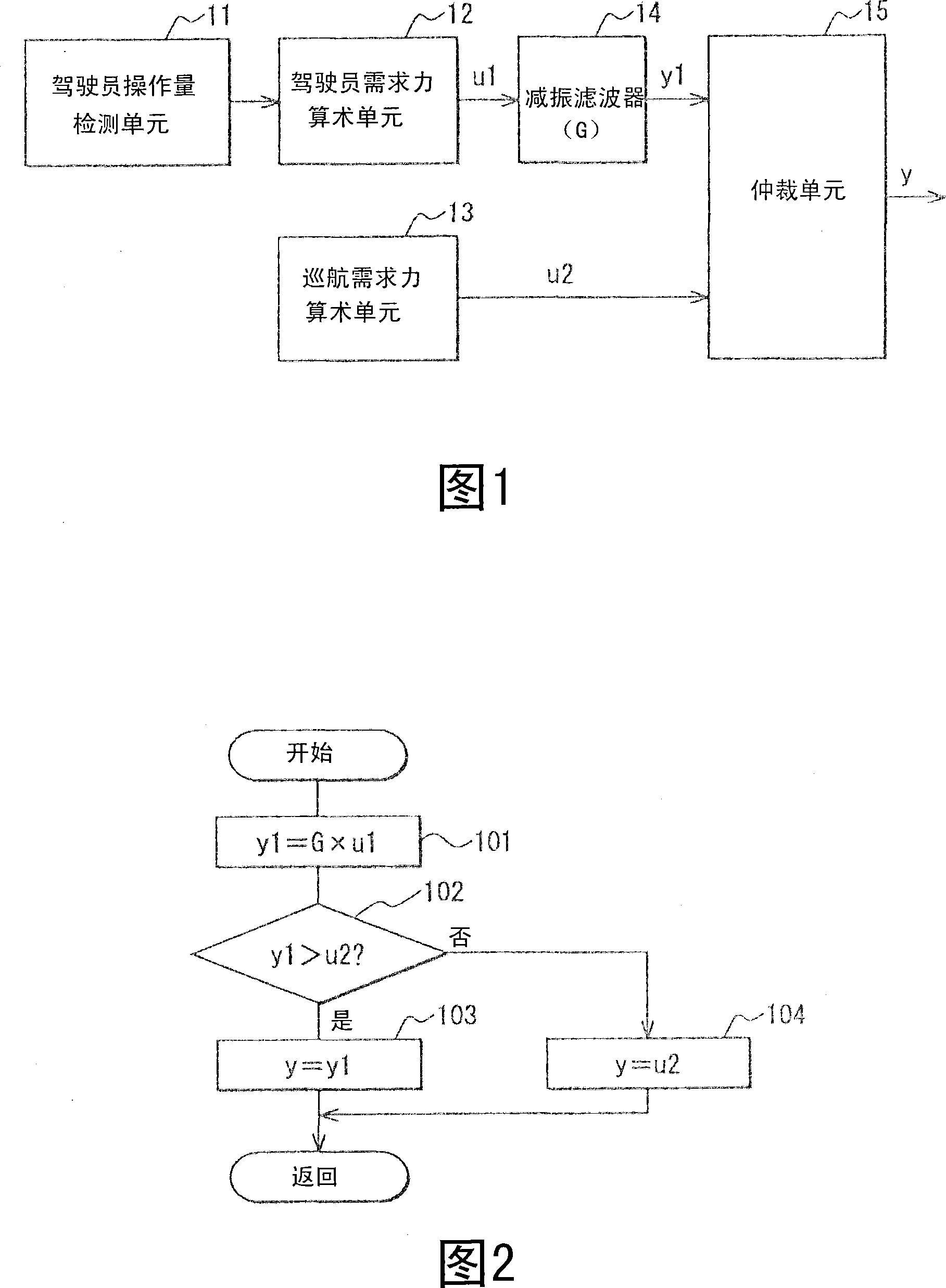
[0035] Referring to FIG. 1, the structure of the vehicle braking-driving force control system will be described.

[0036] The driver's operation amount detection unit 11 is constituted by sensors for detecting driver's operation amount such as an accelerator position, a brake position, and a steering angle. More specifically, the driver's operation amount includes the step amount of the accelerator pedal, the step amount of the brake pedal, and the steering angle of the steering wheel. Instead of accelerator position, throttle position may be detected. In addition, instead of the braking position, the oil pressure of the master cylinder may be detected.

[0037] The driver required braking-driving force arithmetic unit (first required force arithmetic unit) 12 arithmetically calculates the driver required braking-driving force u1 based on the driver's operation amount detected by the driver's operation amount detecting unit 11 . This driver's required braking-driving force i...

no. 2 example

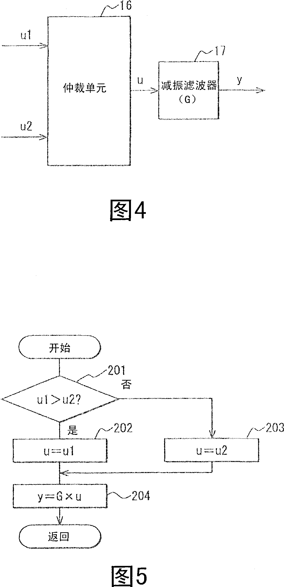
[0059] In the second embodiment of the present invention shown in FIGS. 7 to 9, the vehicle controller is composed of a driver demand force arithmetic unit (first demand force arithmetic unit) 21, a cruise demand force arithmetic unit (second demand force arithmetic unit) ) 22, a first arbitration unit 23, a vibration reduction filter 24 and a second arbitration unit 25. The driver's demand force arithmetic unit 21 arithmetically calculates the driver's demand force u1 (first demand force) including components that cause vibration of the suspension components of the vehicle. The cruise demand force arithmetic unit 22 arithmetically calculates the cruise demand force u2 (second demand force) excluding components that cause vibrations of the suspension components of the vehicle. The first arbitration unit 23 compares the driver demand force u1 and the cruise demand force u2, thereby selecting one of these demand forces u1, u2 as the temporary demand force u. The damping filter ...

no. 3 example

[0070] In the second embodiment described above, the arbitration system of the second arbitration unit 25 is switched according to the operation mode. However, in this third embodiment, at step 305 a of FIG. 10 , the second arbitration unit 25 compares the driver demand force u1 with the cruise demand force u2 . When the driver demand force u1 is greater than the cruise demand force u2, the routine proceeds to step 306a, where the second arbitration unit 25 selects the filtered temporary demand force y1 as the final demand force y. The filtered temporary demand force y1 is generated by filtering the temporary demand force u selected by the first arbitration unit 23 with the damping filter 24 . In contrast, at step 305a, when the driver demand force u1 is equal to or less than the cruise demand force u2, the routine proceeds to step 307a, in which the second arbitration unit 25 converts the temporary demand force u selected by the first arbitration unit 23 to It is selected as...


PUM


Abstract

A controller controls braking force and driving force of a vehicle, in accordance with demand force. The controller includes a first and second demand force arithmetic units (12, 13) for arithmetically calculating first and second demand force (u1, u2). The first demand force (u1) includes a factor inducing vibration in suspended components of the vehicle. The second demand force (u2) substantially excludes the factor inducing vibration in suspended components of the vehicle. A vibration damping filter (14) reduces the factor from a waveform of the first demand force (u1), thereby producing post-filter demand force (y1). An arbitration unit (15) compares the post-filter demand force (y1) with the second demand force (u2), thereby selecting one of the post-filter demand force (y1) and second demand force (u2) as final demand force (y).

Description

[0001] Cross References to Related Applications [0002] This application is based on and incorporated herein by reference to Japanese Patent Application No. 2005-109340 filed on April 6, 2005. technical field [0003] The present invention relates to a controller and method for controlling driving force and braking force of a vehicle. Background technique [0004] JP-A-2004-168148 discloses an optimal control operation for limiting vehicle vibration. In this structure, the braking force generated in the engine and the driving force generated in the brake device are corrected so as to limit the vibration generated in the vehicle body. The braking force and driving force are corrected using a dynamic model that is a dynamic model of vehicle vibration. Such vibrations of the vehicle include, for example, vibrations of vehicle tires, vibrations generated by non-suspension components under which the vehicle is suspended, and vibrations applied to the vehicle body as suspension...

Claims


Application Information

Patent Timeline
Patent Type & Authority Applications(China)
IPC IPC(8): B60T8/172B60W50/08B60G17/0195B60T8/00B60T8/173B60W10/04B60W10/06B60W10/18B60W10/188B60W30/00B60W30/18F02D29/02F02D45/00
CPCB60T8/172B60W30/20B60W2050/0052B60W50/06B60W30/18
Inventor 中井康裕河原研司稻垣匠二高松秀树
Owner DENSO CORP
Features
  • R&D
  • Intellectual Property
  • Life Sciences
  • Materials
  • Tech Scout
  • Unparalleled Data Quality
  • Higher Quality Content
  • 60% Fewer Hallucinations
Learn More