Centralized type sunshade refrigerating and heating system and operation method thereof

A refrigeration system and centralized technology, applied in hot water central heating systems, air conditioning systems, heating systems, etc., can solve the problem of slow temperature regulation, not meeting the requirements of national household measurement, and ground furniture affecting the effect of heat dissipation and other problems, to achieve the effect of low cost and high heating and cooling efficiency

Inactive Publication Date: 2007-08-01
MOMA CHINA CO LTD
View PDF0 Cites 16 Cited by
  • Summary
  • Abstract
  • Description
  • Claims
  • Application Information

AI Technical Summary

Problems solved by technology

[0003] According to the traditional method, a set of terminal heat dissipation facilities is installed in winter, and a split air conditioning system is installed in summer, which itself is a waste of investment
The traditional floor heating method is only suitable for heating in winter, and the effect of cooling in summer is not good, and the placement of floor furniture will affect the effect of heat dissipation; and the pipes are directly embedded in the structural plate, making it impossible to adjust the room temperature by household. Possibly, because it heats the structural plate through the tube, and then transfers heat to the room through the structural plate, it has strong thermal inertia, and the speed of temperature adjustment is very slow, which does not meet the national household measurement requirements. In the future, the pipe will need to be repaired or replaced It cannot be completed, and it is not advocated by the design code of our country to bury the pipe in the structural plate
If the fan coil system commonly used in office buildings is used, it is obviously too expensive to use it in residential projects, and the floor height of the residential buildings does not allow

Method used


Image

  • Centralized type sunshade refrigerating and heating system and operation method thereof
  • Centralized type sunshade refrigerating and heating system and operation method thereof
  • Centralized type sunshade refrigerating and heating system and operation method thereof

Examples


Embodiment 1

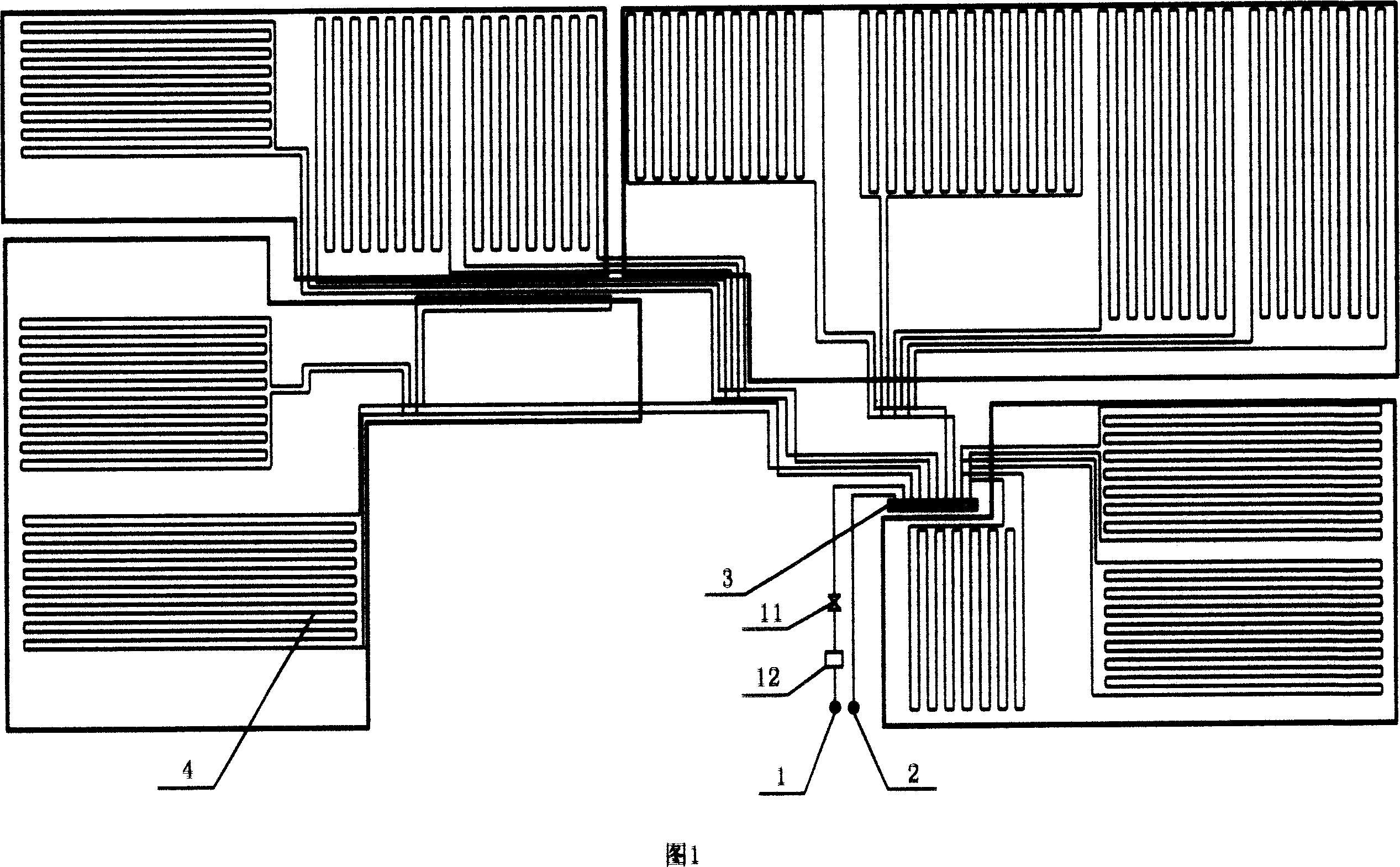
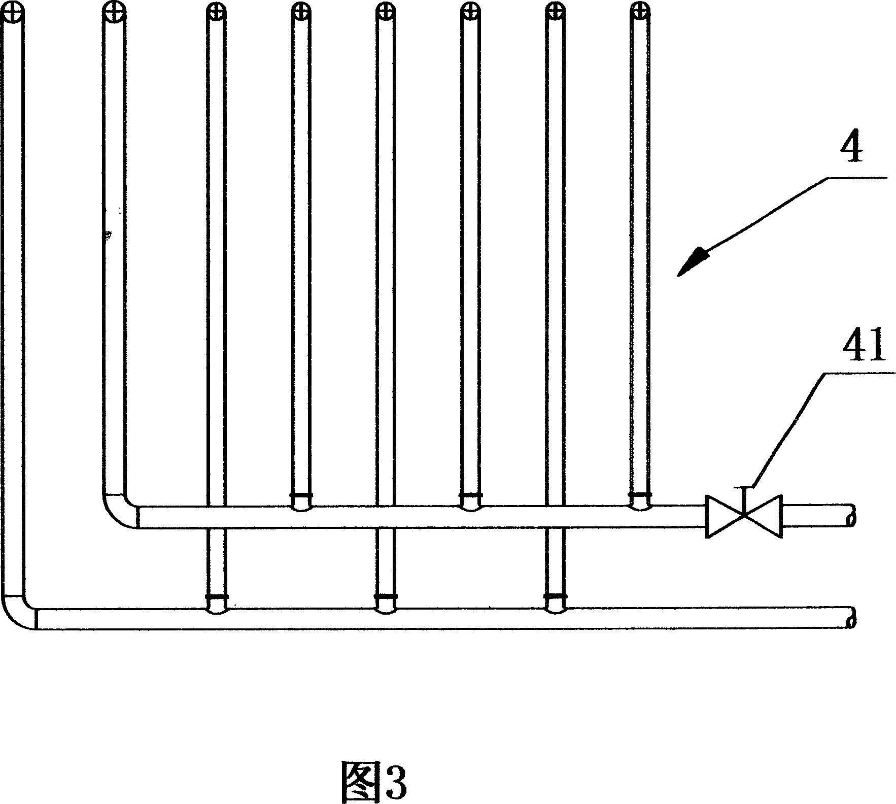
[0017] Referring to Figures 1, 2, and 3, the centralized ceiling heating and cooling system is composed of a centralized water supply pipe 1, a centralized drain pipe 2, a heat medium distribution device 3, and a heating and cooling pipeline 4; the heating and cooling pipeline 4 is located in In the plastering layer 6 below each indoor ceiling 5, in order to fix the heating and cooling pipeline, a steel mesh 61 for fixing the heating and cooling pipeline is also arranged in the plastering layer, and the steel mesh 61 is fixed on the ceiling 5; the centralized water supply pipe 1 It is connected with the heat medium collecting and distributing device 3 , and the heat medium collecting and distributing device 3 is connected with each heating and cooling pipeline 4 , and the centralized drain pipe 2 is also connected with the heat medium collecting and distributing device 3 .

[0018] In order to make the heating and cooling efficiency higher, the heating and cooling pipeline 4 is...

Embodiment 2

[0023] Referring to Figures 1, 2, and 3, the centralized ceiling heating and cooling system is composed of a centralized water supply pipe 1, a centralized drain pipe 2, a heat medium distribution device 3, and a heating and cooling pipeline 4; the heating and cooling pipeline 4 is located in In the plastering layer 6 below each indoor ceiling 5, in order to fix the heating and cooling pipeline, a steel mesh 61 for fixing the heating and cooling pipeline is also arranged in the plastering layer, and the steel mesh 61 is fixed on the ceiling 5; the centralized water supply pipe 1 It is connected with the heat medium collecting and distributing device 3 , and the heat medium collecting and distributing device 3 is connected with each heating and cooling pipeline 4 , and the centralized drain pipe 2 is also connected with the heat medium collecting and distributing device 3 .

[0024] In order to make heating and cooling more efficient, the heating and cooling pipeline 4 is a plas...

Embodiment 3

[0029] Referring to Figures 1, 2, and 3, the centralized ceiling heating and cooling system is composed of a centralized water supply pipe 1, a centralized drain pipe 2, a heat medium distribution device 3, and a heating and cooling pipeline 4; the heating and cooling pipeline 4 is located in In the plastering layer 6 below each indoor ceiling 5, in order to fix the heating and cooling pipeline, a steel mesh 61 for fixing the heating and cooling pipeline is also arranged in the plastering layer, and the steel mesh 61 is fixed on the ceiling 5; the centralized water supply pipe 1 It is connected with the heat medium collecting and distributing device 3 , and the heat medium collecting and distributing device 3 is connected with each heating and cooling pipeline 4 , and the centralized drain pipe 2 is also connected with the heat medium collecting and distributing device 3 .

[0030] In order to make the heating and cooling efficiency higher, the heating and cooling pipeline 4 is...


PUM


Abstract

The invention relates to an integrated ceiling heating refrigerating system and relative operation. The invention is formed by an integrated water tube, an integrated water discharge tube, a hot medium distributor and a heating refrigerating tube. The heating refrigerating tube is arranged in the floated coat under the ceiling of each room as fixed heating refrigerating tube; the floated coat is arranged with a steel bar network for fixing the heating refrigerating tube; the steel bar network is fixed on the ceiling; the integrated water tube is connected with the hot medium distributor connected with each heating refrigerating tube; the integrated water discharge tube is connected with the hot medium distributor. The invention can avoid dew on the ceiling caused by too low temperature of refrigerating water in summer, while the water temperature of refrigerating tube is 18-20/23-25Deg. C, and the water temperature is 39-41/29-31Deg. C of heating tube in winter. The invention has low cost, non pollution and high efficiency.

Description

technical field [0001] The present invention relates to a heating and cooling system and its operating method; more specifically, the present invention relates to a centralized ceiling heating and cooling system and its operating method. Background technique [0002] At present, in the northern part of my country, heating facilities are installed in newly-built residences. For the consideration of energy saving, the country still advocates setting up a central heating system. That is to say, a centralized heat source is established, and the heat is transmitted to the user's terminal equipment by using the pipe network. Most of the terminal equipment still use various radiator products. However, for cooling in summer, because there are no regulations and no suitable terminal facilities, most houses do not have central cooling equipment installed. Many new houses rely on the installation of split air conditioners in each household to solve the cooling problem by themselves. T...

Claims


Application Information

Patent Timeline
Patent Type & Authority Applications(China)
IPC IPC(8): F24F3/06F24D3/14F24F5/00F24F13/30
Inventor 茹万晔陈音
Owner MOMA CHINA CO LTD
Why Eureka
Try Eureka