Zoom lens

A zoom lens and lens technology, which is applied in the field of zoom lenses, can solve the problems of increasing the diopter of the lens group and increasing the fluctuation of aberrations, and achieves the effects of increasing miniaturization and reducing costs.

Inactive Publication Date: 2007-08-01
ASIA OPTICAL CO INC
View PDF0 Cites 13 Cited by
  • Summary
  • Abstract
  • Description
  • Claims
  • Application Information

AI Technical Summary

Problems solved by technology

However, increasing the diopter of each lens group will also cause aberration fluctuations to become larger with the zooming process and it is difficult to make good corrections

Method used


Image

  • Zoom lens
  • Zoom lens
  • Zoom lens

Examples


Embodiment Construction

[0042] First of all, it should be pointed out that although in the embodiments described below, the zoom lens of the present invention is used as an optical projection lens of a projection device, the zoom lens of the present invention can also be used as an optical imaging lens in an imaging device .

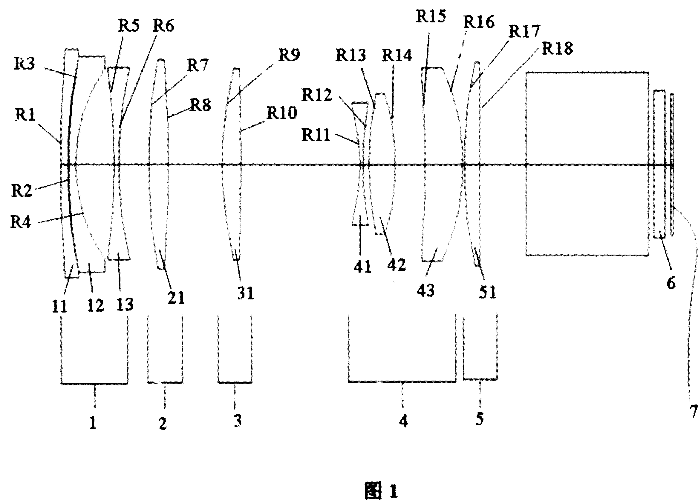
[0043]Fig. 1 is an optical structure diagram of the zoom lens of the present invention, showing the optical structure of the zoom lens positioned at the front end of the optical device at the wide-angle end state. The zoom lens of the present invention is composed of five lens groups, that is, from the object side (enlargement side, the enlarged side of the projection system) to the image plane side (reduction side, the reduced side of the projection system) sequentially includes the first lens Group 1, second lens group 2, third lens group 3, fourth lens group 4 and fifth lens group 5, wherein the first lens group 1 has a negative diopter, the second lens group 2 has a positiv...


PUM


Abstract

This invention discloses one micro variable focus lens head, which orderly comprises negative diopter first lens set, positive diopter second lens set, positive third lens set, positive fourth lens set and positive fifth lens set, wherein, when the variable focus lens head changes from remote distance; the fourth lens set moves from object side to picture side. This invention adopts negative, positive, positive, positive and positive sets of lens structure to form short and compact variable lens head system.

Description

【Technical field】 [0001] The invention relates to a zoom lens, in particular to a zoom projection lens with miniaturization, high resolution and long back focal length which can be applied in an optical projection system. 【Background technique】 [0002] As one of the core components of the imaging and projection system, the primary performance index of the optical lens is to meet the requirements of high zoom ratio and high resolution. Usually, a high zoom ratio lens is realized by multi-group lens groups, multiple lenses, and a longer lens length type, and special low dispersion lenses and aspheric lenses are added to meet the resolution requirements. Existing zoom lenses are generally designed for imaging purposes, so the back focal length (back focal length) is usually not long, but it can meet the requirements of imaging in general photography. However, for the optical projection system, the existing general zoom lenses often cannot be used in the optical projection sys...

Claims


Application Information

Patent Timeline
IPC IPC(8): G02B9/60G02B15/14G02B13/18
Inventor 郭仲渊
Owner ASIA OPTICAL CO INC
Why Eureka
Try Eureka