
High-definition plasma display panel with enlarged discharge space

A high-definition, display panel technology, used in static indicators, instruments, solid cathode components, etc., can solve the problems of reducing discharge efficiency and power efficiency, increasing discharge voltage, and narrowing discharge space, so as to improve discharge efficiency and Efficiency of power supply, increase of discharge space, effect of reducing the loss of charged particles

Inactive Publication Date: 2007-08-08
LG ELECTRONICS(NANJING) PLASMA CO LTD
View PDF0 Cites 1 Cited by
  • Summary
  • Abstract
  • Description
  • Claims
  • Application Information

AI Technical Summary

Problems solved by technology

[0012] However, when such grid-type barriers are used, the unit discharge cell (cell) is surrounded by the horizontal barriers 126 and the vertical barriers 123, and is formed with high-definition specifications. Therefore, the discharge cell itself is very narrow ( cell) The internal discharge space will become narrower, and most of the charged particles in the plasma will be lost on the surface of the interlayer, reducing the discharge efficiency and power supply efficiency, and the discharge voltage will increase

Method used

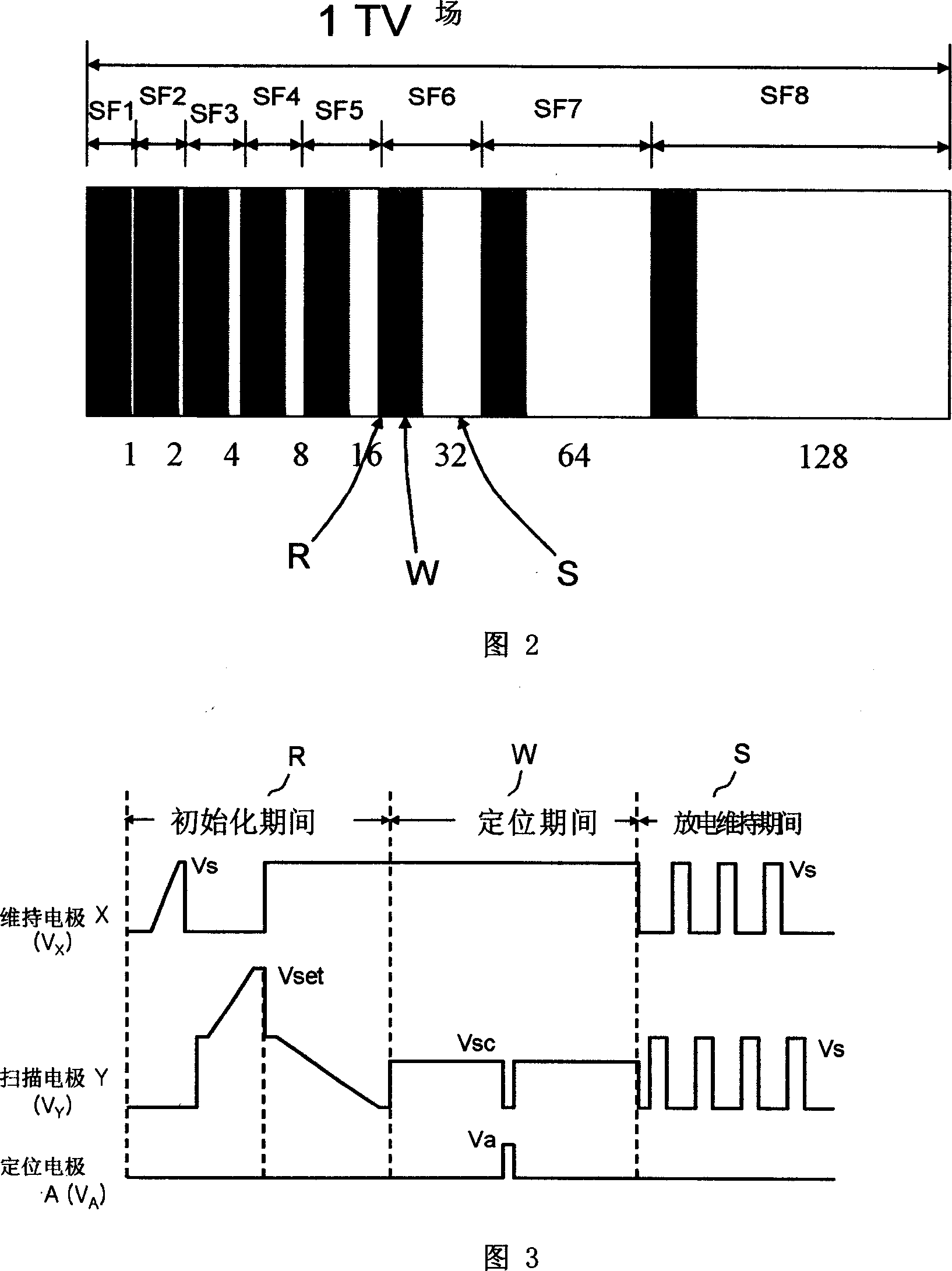
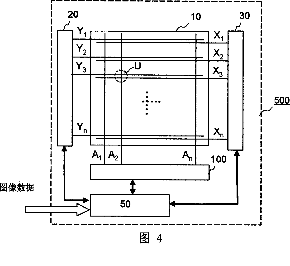

Image

  • High-definition plasma display panel with enlarged discharge space
  • High-definition plasma display panel with enlarged discharge space
  • High-definition plasma display panel with enlarged discharge space

Examples


Embodiment Construction

[0046] Hereinafter, preferred embodiments are given, and detailed descriptions are given in conjunction with the accompanying drawings.

[0047] Fig. 6 is a schematic diagram of the PDP structure in the first embodiment of the present invention. The structure of the PDP in this embodiment improves the distribution of a plurality of sustain electrodes (X) and scan electrodes (Y) arranged on the upper plate 210. Unlike the prior art in FIG. 5 , a pair of sustain electrodes ( X) and a pair of scanning electrodes (Y). That is, adjacent upper and lower discharge cells (cells) are symmetrical to each other, and the sustain electrode (X) of the upper discharge cell (cell) and the lower discharge cell (cell) are not scan electrodes (Y) but sustain electrodes (X). ) adjacent.

[0048] The structure of this embodiment is simply repeated alternately with the sustain electrodes (X) and scan electrodes (Y) in the upper plate 110. As shown in FIG. 5, the sustain electrodes (X) and the sca...


PUM


Abstract

The invention discloses one high resolution plasma display panel to expand discharge space, which comprises multiple sustain electrodes and scanning electrodes, wherein, multiple sustaining electrodes and scanning electrodes formed by two scanning electrodes nearby; forming level isolation layer to divide upper and down discharge units; in above adjacent two sustain electrode and two scanning electrodes, the near two scanning electrodes are set with above isolation layer.

Description

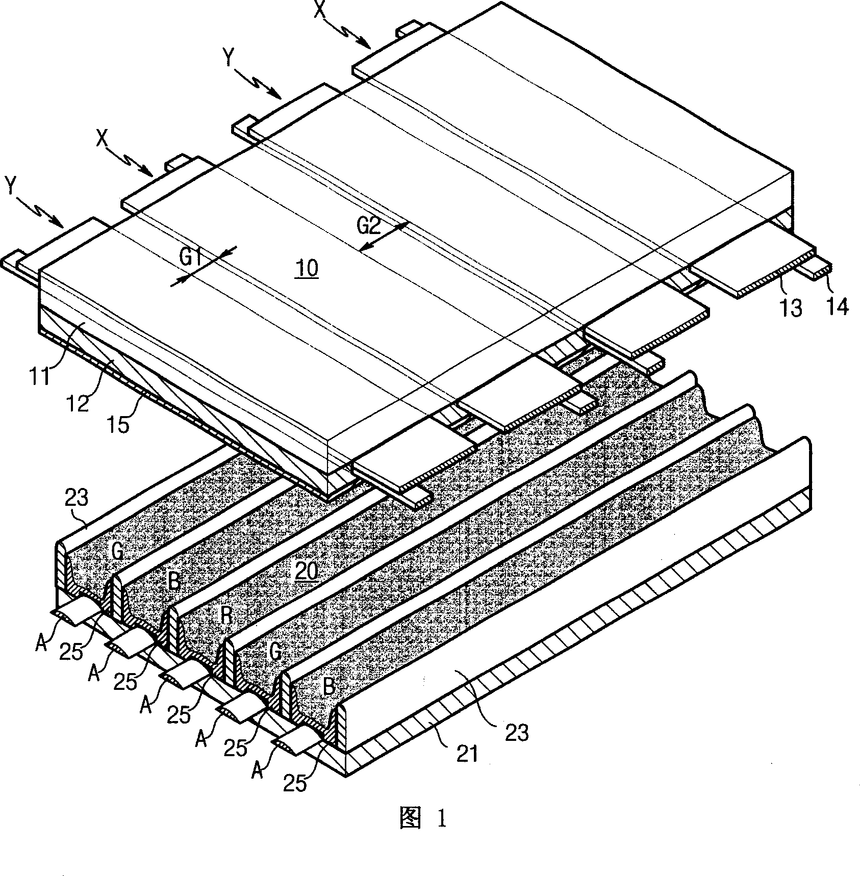
1. Technical field [0001] The present invention relates to a plasma display panel (hereinafter referred to as 'PDP'), and specifically to a plasma display panel (hereinafter referred to as 'PDP'), which is applicable to a high-definition PDP, fully ensures a discharge space in a discharge cell (cell), and reduces charging. Particle loss, high-definition plasma display panels that improve discharge efficiency and power supply efficiency and expand discharge space. 2. Background technology [0002] Fig. 1 is the structural exploded schematic diagram of existing general PDP, and the existing PDP in the figure is by upper board (or ' front board ') 10, and the lower board (or ' back board') 20 that is parallel with above-mentioned upper board 10 connected to form. [0003] The upper plate 10 includes: a plurality of sustain electrodes (X) and scan electrodes (Y) arranged in parallel on the glass substrate 11, and the lower plate 20 includes: the sustain electrodes and the scan ...

Claims


Application Information

Patent Timeline
IPC IPC(8): H01J17/49H01J17/04H01J17/16G09G3/28
Inventor 闵丙国
Owner LG ELECTRONICS(NANJING) PLASMA CO LTD
Learn More