Supercharge Your Innovation With Domain-Expert AI Agents!

Laser cutting method

一种激光切割、轮廓的技术,应用在激光焊接设备、涡轮机、制造工具等方向,能够解决溅回、不能避免熔融的金属、不理想等问题

Active Publication Date: 2007-08-15
SN DETUDE & DE CONSTR DE MOTEURS DAVIATION (S N E C M A)
View PDF0 Cites 1 Cited by
  • Summary
  • Abstract
  • Description
  • Claims
  • Application Information

AI Technical Summary

Problems solved by technology

[0011] A simple anti-CO 2 A guard made of metal at the wavelength of the beam is not ideal because it cannot prevent molten metal from splashing back onto the rear surface of the inner shell

Method used


Image

  • Laser cutting method
  • Laser cutting method

Examples


Embodiment Construction

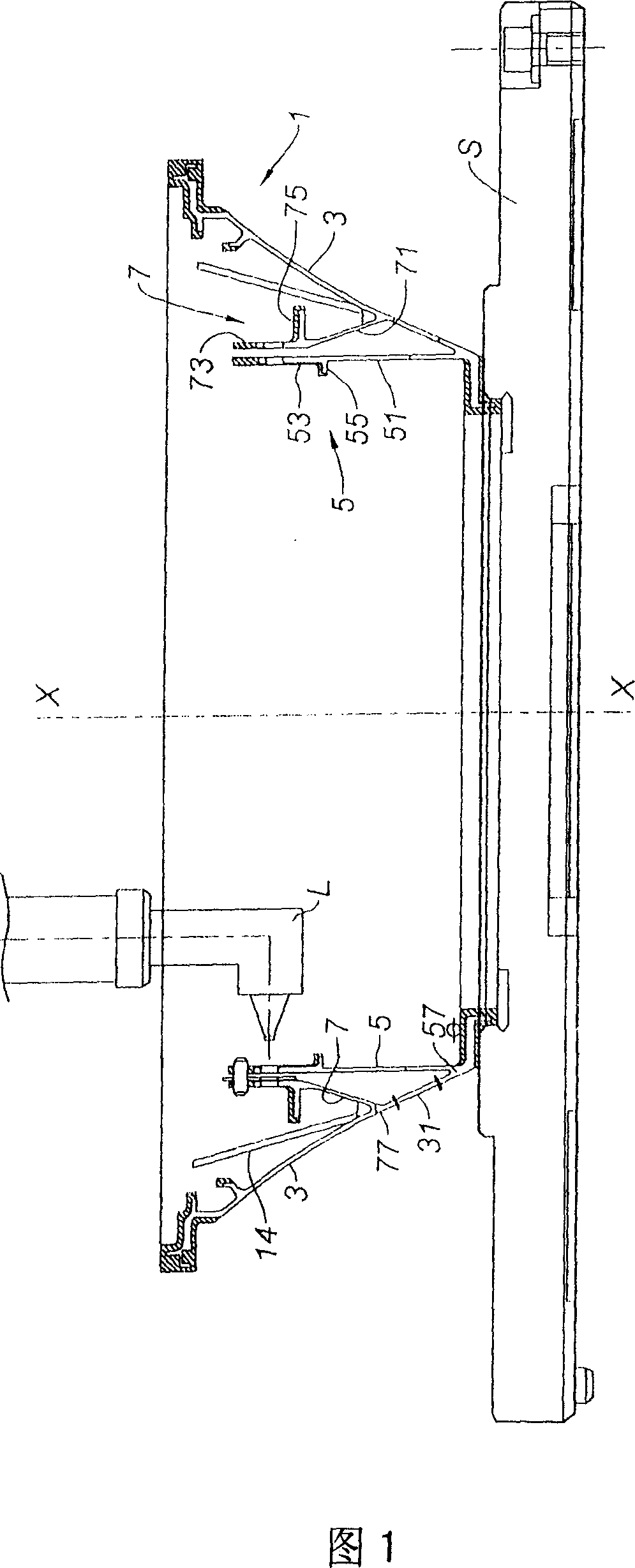
[0026] The invention is suitable for components of high pressure distributor housings of gas turbine engines. This is where the mount is placed downstream of the combustion chamber of the engine and consists of receiving the combustion gases coming out of the combustion chamber and directing them into the high pressure turbine wheel which is arranged axially downstream of the stage of distribution vanes which are arranged at their ends department. In FIG. 1 , the manufactured housing 1 is secured to a support S for various machining and assembly operations.

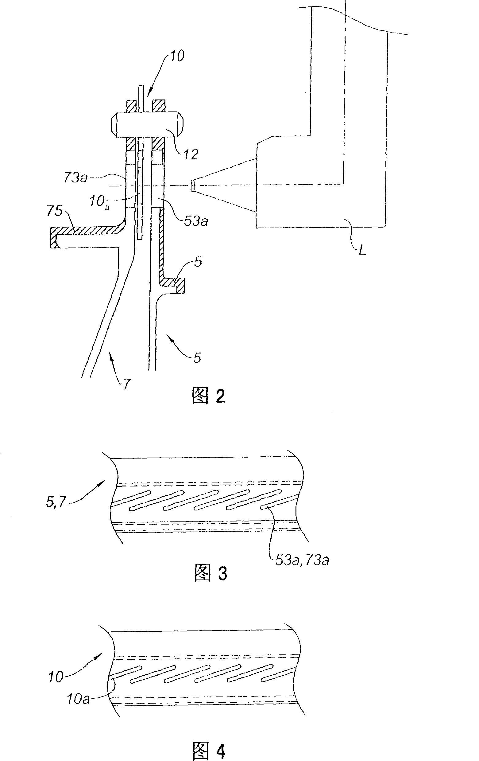
[0027] This casing comprises a common frusto-conical part 3 with axis xx. Various parts constituting the turbine stator are welded or machined on part 3 . In particular, this casing consists of two coaxial casings 5 ​​and 7 between which there is an annular passage with axis xx for the combustion gases coming from the combustion chamber. This annular channel communicates on one side with a hole 31 cut in the wall of th...


PUM


Abstract

The present invention relates to a method for laser cutting at least a first aperture ( 53 a) in a first metal plate ( 5 ) in the presence of a second metal plate ( 7 ) placed parallel to and a short distance from the first plate ( 5 ) and having a second aperture ( 73 a), the outline of which is in line with the outline of the aperture ( 53 a) to be cut, wherein a plate forming a protective means ( 10 ), of defined thickness and having a third aperture ( 10 a) whose outline is inwardly offset with respect to the outline of the second aperture ( 73 a), is placed between the first and second plates ( 5 and 7 ).

Description

technical field [0001] The invention relates to the field of cutting metal parts with lasers, such as CO 2 laser. Background technique [0002] In order to manufacture metal parts with complex geometries by machining or cutting, we have to invent a special method. An example is when manufacturing a driving fluid distribution casing to meet specific specifications in a turbine, such as a gas turbine engine. [0003] What this enclosure entails is the general shape of a frusto-cone, on the inwardly facing surface fastened two coaxial shells of slightly different diameters. On the one hand openings are cut near the free edge of the outer shell and on the other hand the inner shell allows stationary fluid distribution vanes to be fixed therein. The openings are radially arranged in pairs. [0004] The problem thus raised is how to cut holes in the inner shell. [0005] There are several techniques that come to mind, but they all suffer from shortcomings: [0006] - For exa...

Claims


Application Information

Patent Timeline
Patent Type & Authority Applications(China)
IPC IPC(8): B23K26/38B23K26/18
CPCF01D25/24B23K26/18F05D2230/13B23K26/38B23K2201/001B23K2101/001
Inventor 多米尼克·布尔丹杰尔姆·马尔提蒂埃里·萨尔杜
Owner SN DETUDE & DE CONSTR DE MOTEURS DAVIATION (S N E C M A)
Features
  • R&D
  • Intellectual Property
  • Life Sciences
  • Materials
  • Tech Scout
  • Unparalleled Data Quality
  • Higher Quality Content
  • 60% Fewer Hallucinations
Learn More