Side lighting back light module

A backlight module, edge-lit technology, applied in optics, nonlinear optics, instruments, etc., can solve the problems of thermal coupling and interactive heat accumulation, and achieve the effect of increasing the divergence path and improving efficiency

Inactive Publication Date: 2007-08-15
AU OPTRONICS CORP
View PDF0 Cites 40 Cited by
  • Summary
  • Abstract
  • Description
  • Claims
  • Application Information

AI Technical Summary

Problems solved by technology

In this way, not only the problem of heat dissipation cannot be solved, b

Method used


Image

  • Side lighting back light module
  • Side lighting back light module
  • Side lighting back light module

Examples


Embodiment Construction

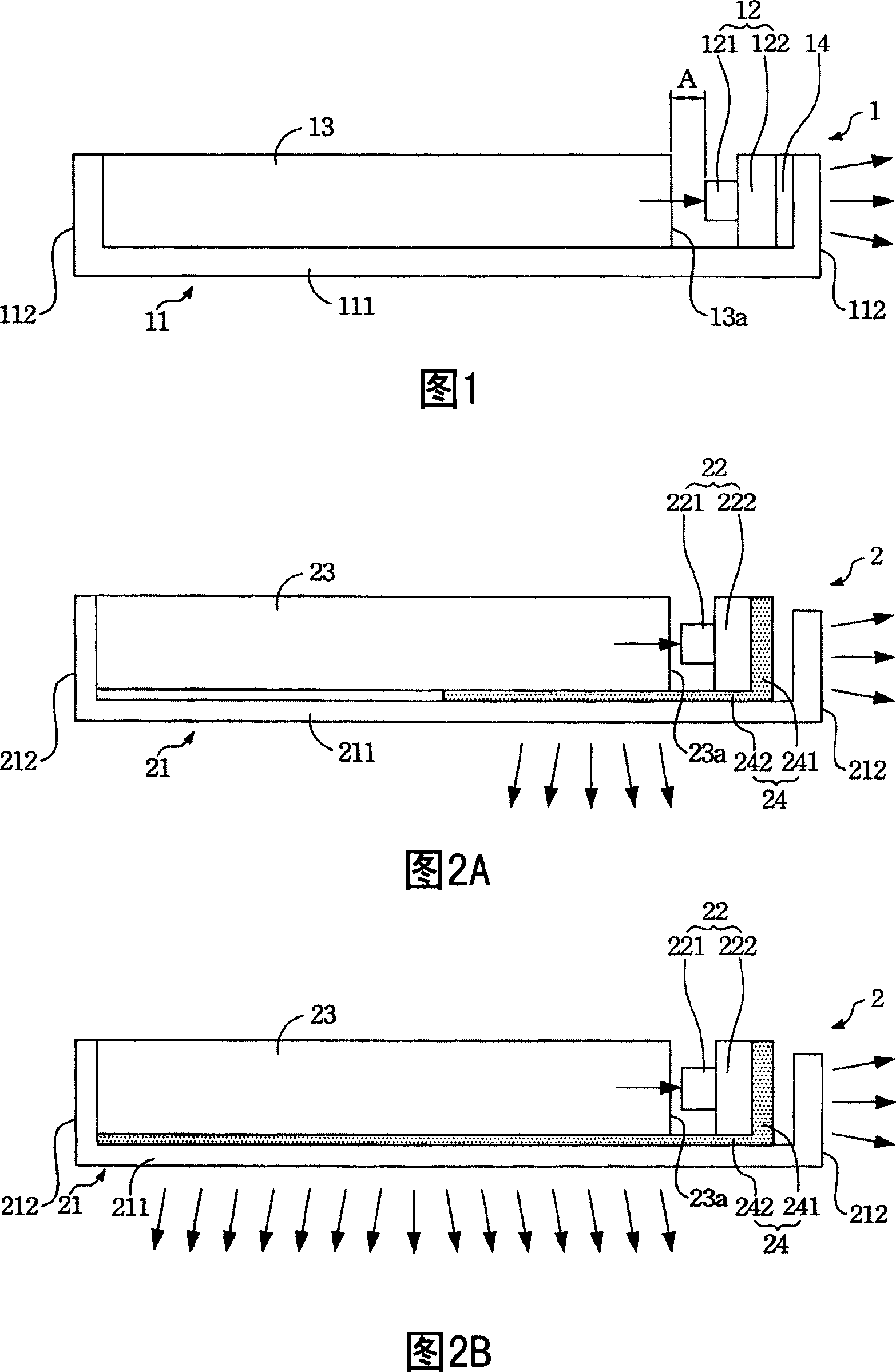
[0050]When the light guide plate 13 in Figure 1 is assembled into the backlight module 1, there is often a gap A between it and the LED 121. Close to LED 121 to provide higher light source utilization efficiency and avoid light leakage. However, the size design of the general frame always reserves some tolerance margins to match the actual processing or assembly tolerances; therefore, the existence of the gap A is difficult to avoid in actual situations. Therefore, in addition to the above-mentioned problem of poor heat dissipation, the known side-light LED backlight module also has the problem that the light incident efficiency needs to be improved.

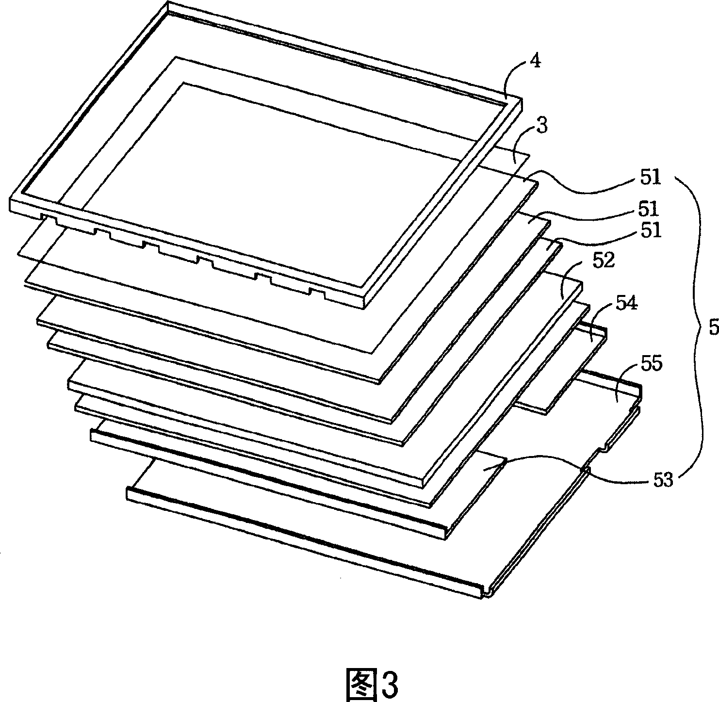
[0051] Please refer to FIG. 2A , which is a side sectional view of an edge type backlight module disclosed by the present invention in a preferred embodiment. The backlight module 2 includes a frame 21 , at least one LED light source group 22 , a light guide plate 23 and a heat conduction structure 24 . The frame 21 is a struc...


PUM


Abstract

This invention relates to one edge type aphototropism module, which comprises one frame rack, one LED light set and one heat guide structure, wherein, the frame rack has bottom and the side wall from bottom; the LED light source set is inside frame near the end of side wall; the heat structure is set between LED light source set and frame; the heat conductive structure also comprises one body part and one extensive part and the body part is between LED light source set and side wall and extensive part is connected to the body part between LED light source set and bottom part.

Description

technical field [0001] The invention relates to a backlight module, in particular to an edge type (Edge Type) backlight module with a cooling device. Background technique [0002] Liquid crystal display (LCD) technology is widely used in computer screens, mobile phones, digital cameras, camcorders, PDAs and other products. LCD panel (LCD panel) is a key display component, but it does not emit light by itself. It needs to be equipped with a backlight module (backlight module) to display. The backlight module is assembled with the LCD panel to form a complete LCD module ( liquid crystal module, LCM). [0003] Please refer to FIG. 1 . FIG. 1 is a side sectional view of a conventional edge type (Edge type) backlight module. The backlight module 1 includes a frame 11 , at least one LED light source group 12 and a light guide plate 13 , wherein the LED light source group 12 is composed of LEDs 121 , a circuit board 122 and a power input device (not shown). The frame 11 is a str...

Claims


Application Information

Patent Timeline
IPC IPC(8): G02F1/1335G02F1/1333G02F1/133
Inventor 林佑撰
Owner AU OPTRONICS CORP
Why Eureka
Try Eureka