High speed arbitrary waveform generator based on FPGA

An arbitrary waveform and generator technology, applied in the field of high-speed arbitrary waveform generators, can solve the problems that the working frequency of digital circuits can only reach a few hundred MHz, and the working frequency of data phase generating circuits and waveform memory cannot reach the working frequency of DAC.

Inactive Publication Date: 2007-08-15
王文华
View PDF0 Cites 36 Cited by
  • Summary
  • Abstract
  • Description
  • Claims
  • Application Information

AI Technical Summary

Problems solved by technology

However, the operating frequency of the digital circuit can only reach a few hundred MHz, that is to say, the operating

Method used


Image

  • High speed arbitrary waveform generator based on FPGA
  • High speed arbitrary waveform generator based on FPGA
  • High speed arbitrary waveform generator based on FPGA

Examples


Embodiment Construction

[0027] The present invention is not limited to the structure and implementation details described or illustrated below, and the present invention can also have other specific embodiments.

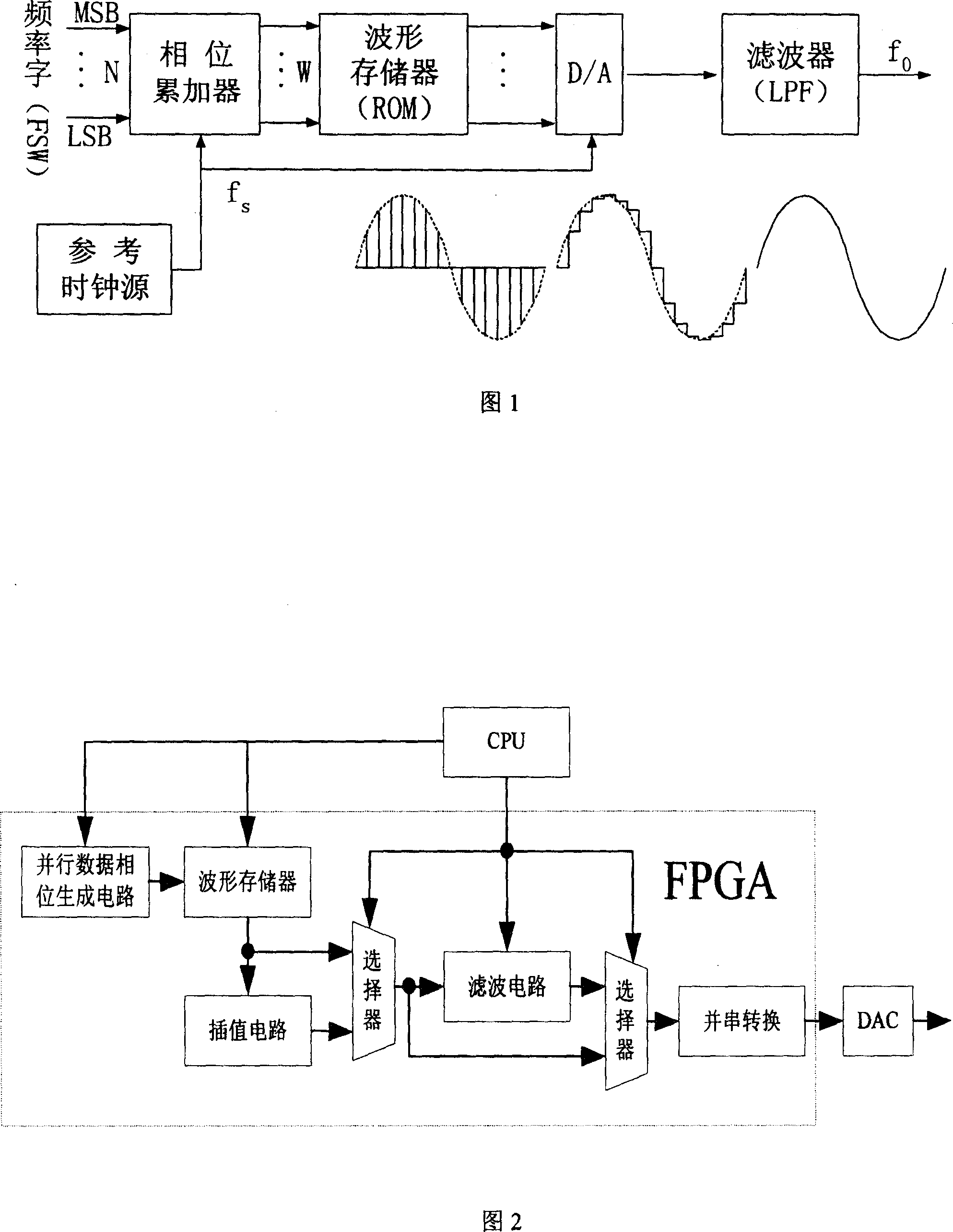
[0028] Fig. 2 has provided the structural block diagram of the present invention, including CPU, FPGA and DAC etc. Among them CPU can be AT91RM9200 of ATMEL company or other. The FPGA can be the FPGA of the stratixII series of altera company, or the FPGA of xilinx company. The following uses the EP2S30 of altera company as an example. The DAC in Figure 2 can be a high-speed DAC from Maxim, or a DAC from AD, such as AD9736.

[0029] The CPU in Figure 2 is mainly used to configure the frequency word in the FPGA, the data in the waveform memory and the parameters of the digital filter circuit. By modifying the frequency word register in FPGA, the system can obtain the output of any frequency, and by modifying the data in the waveform memory, the system can obtain the output of arbitrary wave...


PUM


Abstract

This invention relates to one high speed random wave generator based on FPGA, which adopts DDS technique with data sample rate more than 1GHz and comprises CPU, parallel data phase generation part, wave shape memory part, plug and filter part, parallel and series conversion circuit and DAC, wherein, the parallel data phase generation adopts parallel process to generate multiple data phase In one time clock to get multiple data; then it uses FPGA series and parallel conversion circuit to output the data to DAC into virtual volume.

Description

technical field [0001] The invention relates to a waveform generator, in particular to a FPGA-based high-speed arbitrary waveform generator. Background technique [0002] The arbitrary waveform generator based on DDS (Direct Digital Synthesis) technology uses high-speed memory as a look-up table, and synthesizes the waveform stored in the memory through high-speed DAC. So it can not only generate common waveforms such as sine, cosine, square wave, triangle wave and sawtooth wave, but also can use various editing methods to generate truly arbitrary waveforms that cannot be generated by traditional function generators. [0003] Although there are many kinds of structures of the DDS system, its basic circuit principle can be expressed in Figure 1. [0004] DDS technology is based on the sampling theorem. It first samples the waveform to be generated, digitizes the sampled value and stores it in the memory as a lookup table, then reads the data through the lookup table, and con...

Claims


Application Information

Patent Timeline
IPC IPC(8): G06F1/03
Inventor 王文华
Owner 王文华
Why Eureka
Try Eureka