Information processing apparatus having memory clock setting function and memory clock setting method

A technology for information processing devices and memory controllers, applied in memory systems, electrical digital data processing, digital data processing components, etc., can solve problems such as increased memory power consumption and inability to fully display the transmission rate, so as to reduce power consumption Effect

Inactive Publication Date: 2009-05-27
FUJITSU CLIENT COMPUTING LTD
View PDF4 Cites 3 Cited by
  • Summary
  • Abstract
  • Description
  • Claims
  • Application Information

AI Technical Summary

Problems solved by technology

[0012] As described above, in recent systems, even if the memory data transfer rate is increased, because other parts may become bottlenecks, the increased transfer rate cannot be fully exhibited, and there is a problem of increased power consumption of the memory due to the increase in the transfer rate

Method used


Image

  • Information processing apparatus having memory clock setting function and memory clock setting method
  • Information processing apparatus having memory clock setting function and memory clock setting method
  • Information processing apparatus having memory clock setting function and memory clock setting method

Examples


Embodiment Construction

[0027] Embodiments of the present invention will be described below with reference to the drawings.

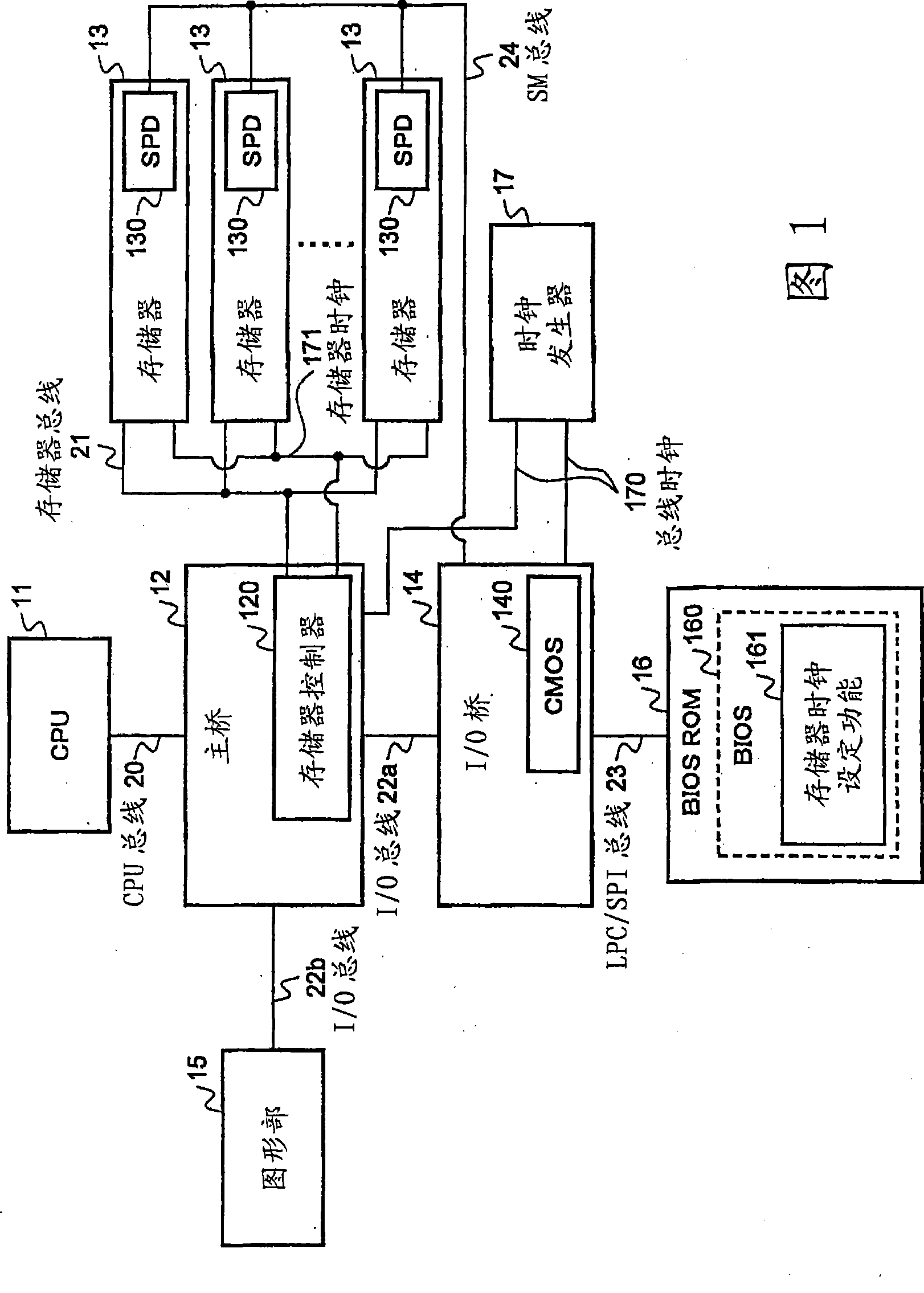
[0028] FIG. 1 is a diagram showing a configuration example of an information processing device according to an embodiment of the present invention. The information processing device includes a CPU 11 , a main bridge 12 , a memory 13 , an I / O bridge 14 , a graphics unit 15 , a BIOS ROM 16 and a clock generator 17 .

[0029] The CPU 11 is a processor that controls a system or device.

[0030] The host bridge 12 is a chip that connects the CPU 11, memory 13, and I / O, and may include a memory controller 120 according to a chipset (platform). In the example of the information processing apparatus shown in FIG. 1 , the host bridge 12 includes a memory controller 120 . In the main bridge 12, the setting of the CPU 11 is performed. The memory controller 120 controls the memory 13 to set the working clock or working timing of the memory 13 .

[0031] The memory 13 is a main storage...


PUM


Abstract

The invention provides an information processing device with a memory clock setting function and a memory clock setting method. The memory clock setting function acquires the band of a memory bus, and acquires the total band of a CPU bus and the I / O buses. When the band of the memory bus is greater than the total band of the CPU bus and I / O buses, the clock rate less than or equal to the current operation clock of a memory is selected so that the band of the memory bus may not be less than the total band of the CPU bus and the I / O buses, and the selected clock rate is set as the operation clock of the memory to a memory controller.

Description

technical field [0001] One embodiment of the present invention relates to a technique for setting an operation clock of a memory, and may include information processing having a memory clock setting function of changing the operation clock setting of the memory according to the bandwidth of a bus connected to a memory controller other than the memory bus. A device, and a memory clock setting method. Background technique [0002] This application claims priority from Japanese Patent Application No. 2007-301663 filed on November 21, 2007, the entire contents of which are hereby incorporated by reference. [0003] Figure 5 is a diagram for explaining an example of a peripheral environment of a memory. exist Figure 5 Among them, the bus connecting CPU 500 and memory controller 510 is called CPU bus 600, the bus connecting I / O bridge 530 and memory controller 510 is called I / O bus 610, and the bus connecting memory controller 510 and memory 520 Referred to as the memory bus 6...

Claims


Application Information

Patent Timeline
Patent Type & Authority Applications(China)
IPC IPC(8): G06F1/08G06F13/16
CPCG06F1/3275Y02B60/1225G06F1/3203Y02D10/00G06F13/16G06F12/00G06F1/08
Inventor 铃木贵善
Owner FUJITSU CLIENT COMPUTING LTD
Why Eureka
Try Eureka