An installation device of the contactor

A technology for installing devices and contactors, applied in substation/switch layout details, electrical components, relay base/housing/cover, etc., can solve the problems of reduced strength, waste of materials, and increased volume of sliders, etc., to achieve installation and Simple and fast disassembly, stable and reliable performance, and the effect of saving materials

Active Publication Date: 2007-08-15
ZHEJIANG CHINT ELECTRIC CO LTD
View PDF0 Cites 9 Cited by
  • Summary
  • Abstract
  • Description
  • Claims
  • Application Information

AI Technical Summary

Problems solved by technology

[0003] For the installation device with the above structure, in order to reserve a cavity for placing the pressure spring on the slider, the volume of the slider must be designed to be large and thick, which wastes both material and space
Its other shortcoming is that the slider and the base are positioned in a buckle manner. When disassembling, a pair of barbs must be forced together to make them release from the card platform, and then the slider can be withdrawn. The barb leaves room for manipulation, and the volume of the slider will increase further
Another disadvantage of it is that since the barb must be elastic, and the entire slider is an integrated design, the slider must be made of a material that is both elastic and high in strength, and the barb will disappear after repeated disassembly. The strength of the material will be reduced, directly affecting the service life of the slider

Method used


Image

  • An installation device of the contactor
  • An installation device of the contactor
  • An installation device of the contactor

Examples


Embodiment Construction

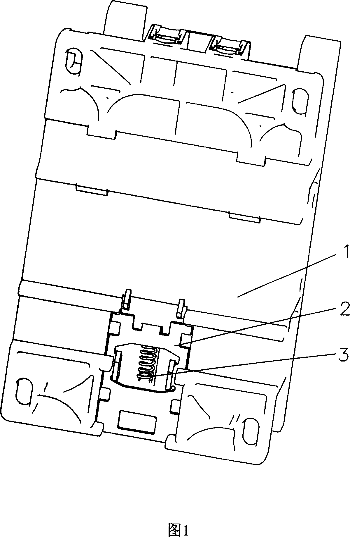
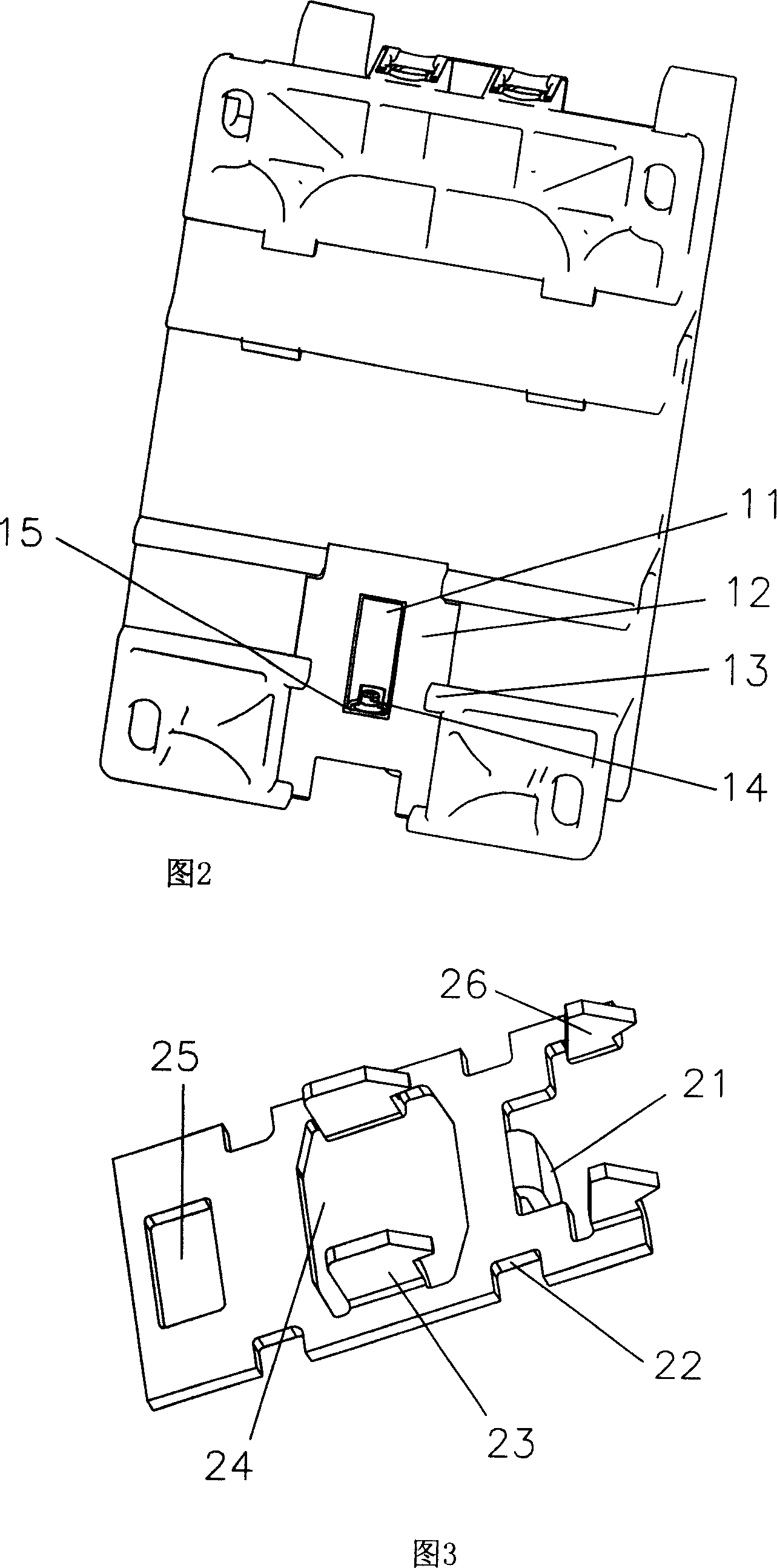
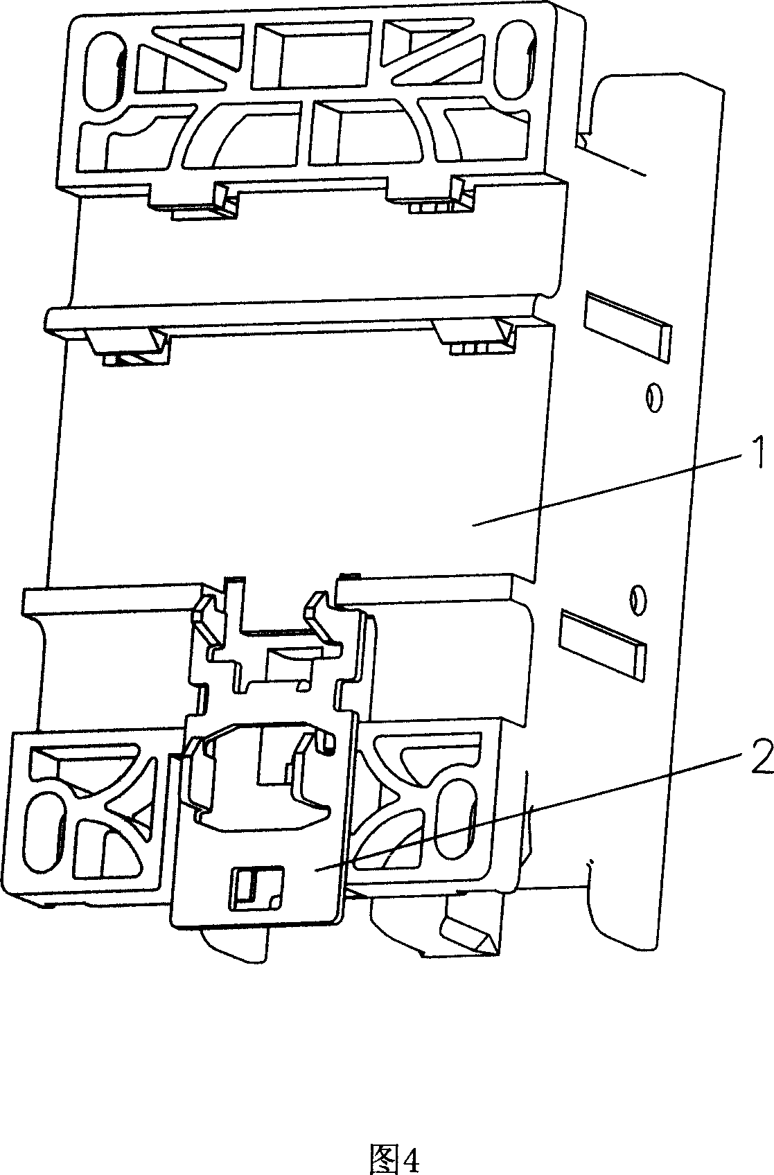
[0017] Referring to FIGS. 1-3 , the contactor installation device of the present invention includes a base 1 , a slider 2 and a compression spring 3 . The bottom surface of the base 1 has a mounting plane 12; the middle part of the mounting plane 12 is provided with a groove 11, and a pair of protrusions 13 are suspended above; the outer end 15 of the groove 11 is also provided with a boss 14 .

[0018] Two sides of the slider 2 are provided with a pair of notches 22 opposite to the protrusion 13 , an opening 24 opposite to the groove 11 is provided in the middle, and a limiting block 21 is provided at the inward end. The compression spring 3 is arranged in the groove 11 , one end is nested on the protruding column 14 , and the other end is pushed against the limit block 21 . The distance between the pair of protrusions 13 above the installation plane 12 and the installation plane 12 is equal to or slightly greater than the thickness of the slider 2 . The outer end of the sl...


PUM


Abstract

The disclosed assembly device for contactor comprises: a base with an assembly plane, a concave slot opened on middle of the plane, a couple of bulges hung above the plane, a slider with two gaps on sides for former bulges, an opening on middle of slider for the slot, a limit-position block on inby end of the slider, a pressing spring set in the slot with two ends on external end of slot and limit-position block. This invention has small size, reliable and convenient to varied material.

Description

technical field [0001] The invention relates to a contactor installation device. Background technique [0002] Existing contactors are usually installed or assembled on a standard guide rail in the form of a slider. The slider is provided with a chamber for placing a compression spring and a pair of barbs in a direction perpendicular to the standard guide rail, and a pair of concave holes on both sides. Groove; a pair of card platforms opposite to the barb and a pair of ribs opposite to the groove are provided at the corresponding position of the bottom end of the contactor. When assembling, put the pressure spring into the cavity of the slider first, then align the groove with the convex edge and push the slider from the inside to the end, when the working slope on the pair of barbs slides over the working slope on the pair of card tables After the inclined surface, the barb stretches to both sides under the elastic force of its own material and is embedded on the card pla...

Claims


Application Information

Patent Timeline
Patent Type & Authority Applications(China)
IPC IPC(8): H01H45/04
CPCH02B1/0523H02B1/052
Inventor 丁景峰张亚莉
Owner ZHEJIANG CHINT ELECTRIC CO LTD
Why Eureka
Try Eureka