Driving device for hybrid car

A technology of hybrid electric vehicles and driving devices, which is applied in the direction of hybrid electric vehicles, power devices, pneumatic power devices, etc., and can solve problems such as difficult to improve motor/generator MG drive efficiency, motor/generator MG drive efficiency reduction, etc.

Inactive Publication Date: 2007-08-15
AISIN AW CO LTD
View PDF1 Cites 42 Cited by
  • Summary
  • Abstract
  • Description
  • Claims
  • Application Information

AI Technical Summary

Problems solved by technology

Therefore, the gap g between the inner peripheral surface of the stator S and the outer peripheral surface of the rotor R has to be set large, and it is difficult to improve the driving efficiency of the motor / generator MG.
[0005] In addition, since the lubricating oil of the starting clutch flows into the motor chamber MV through the spline s and is stirred by the rotor R, there is a concern that the driving efficiency of the motor / generator MG may decrease.

Method used


Image

  • Driving device for hybrid car
  • Driving device for hybrid car
  • Driving device for hybrid car

Examples


Embodiment Construction

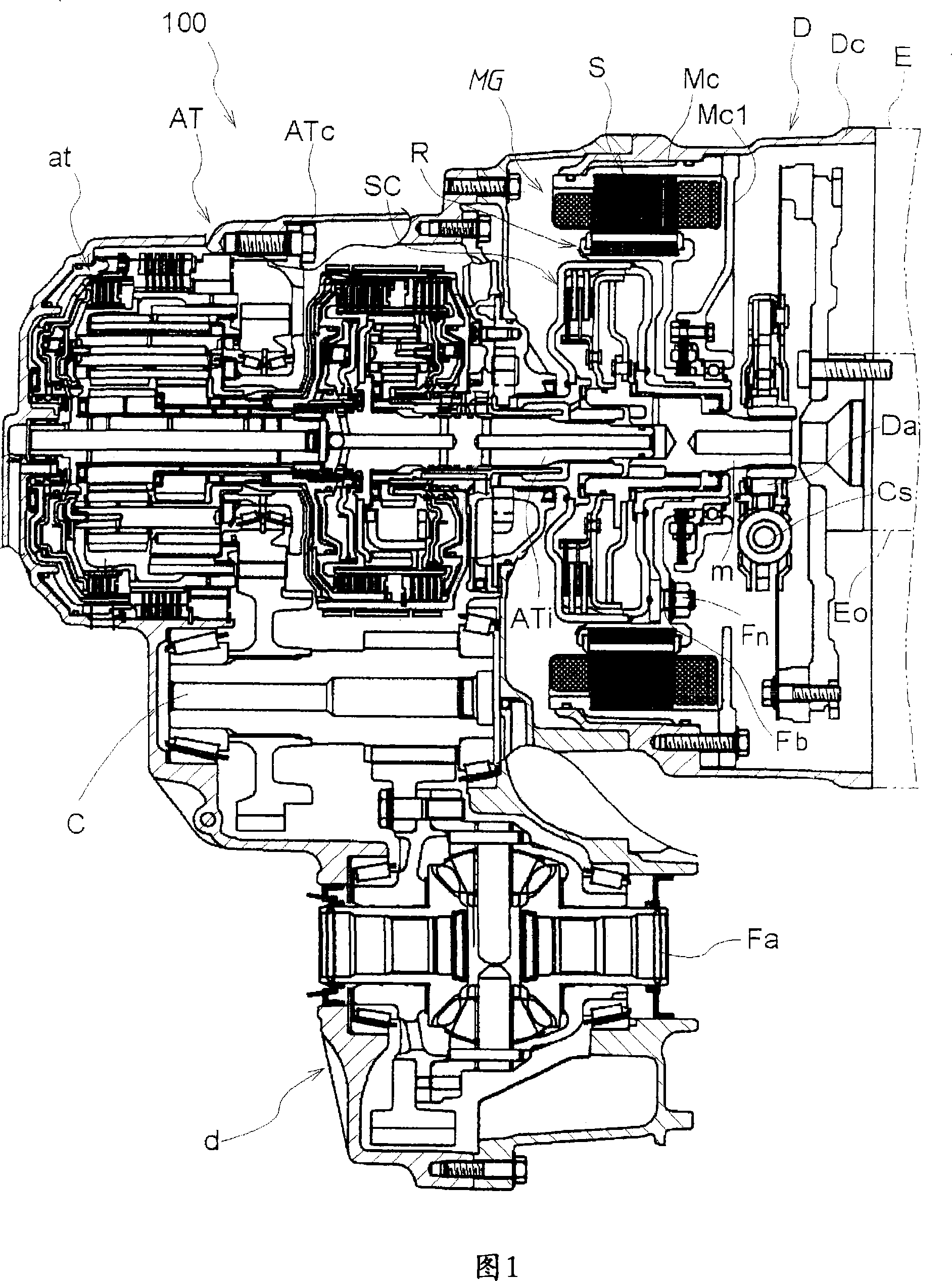
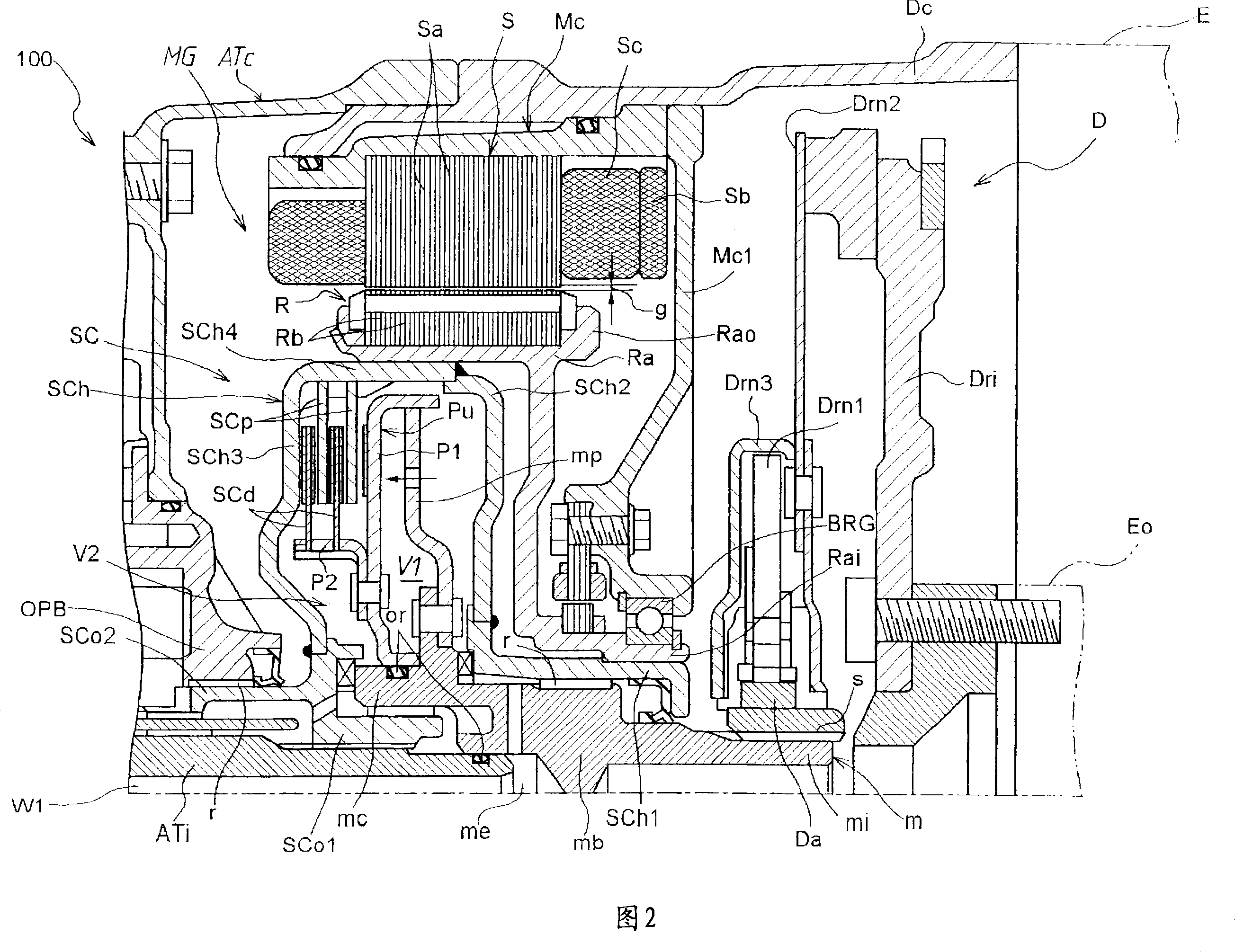
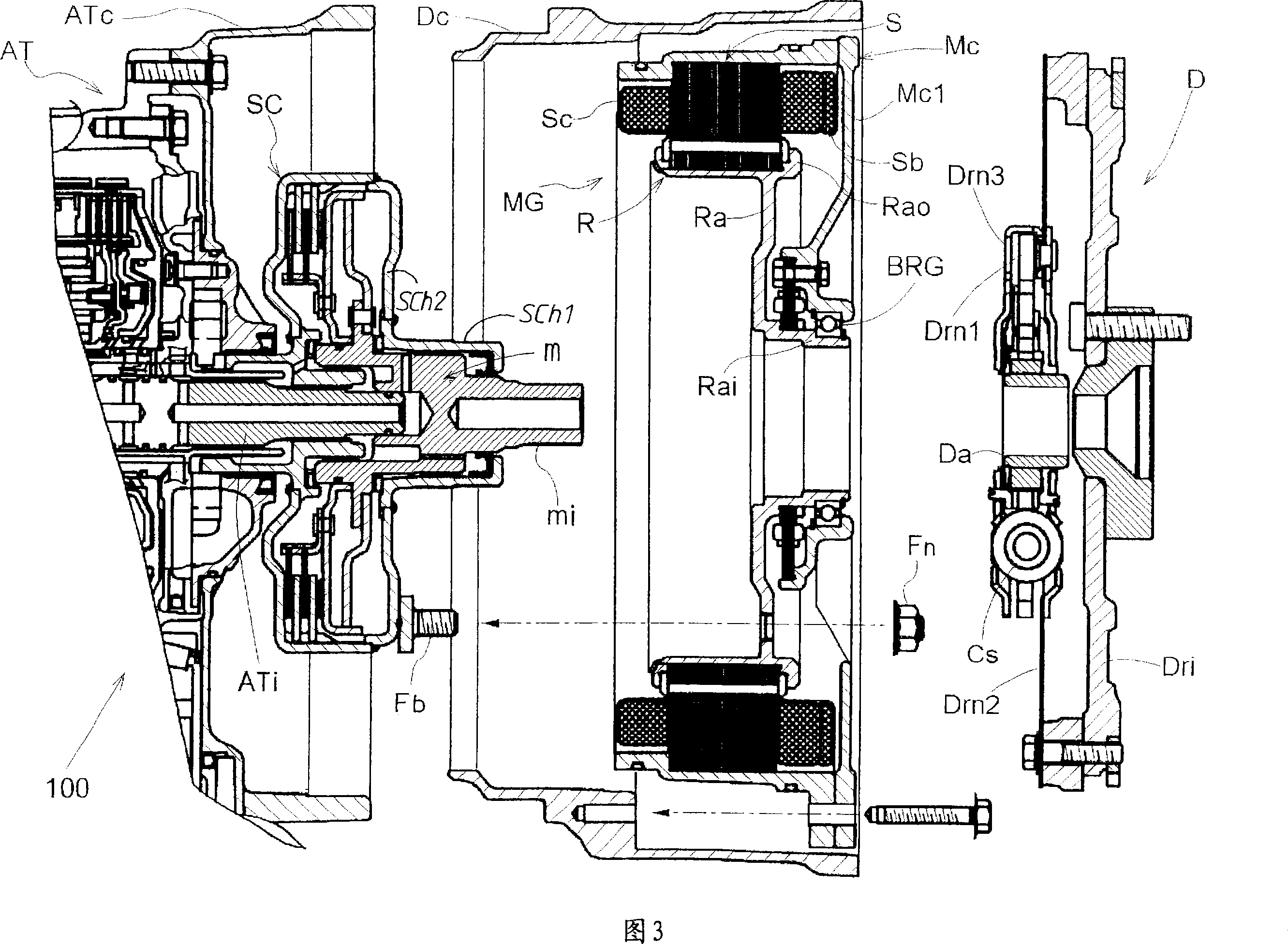
[0013] Hereinafter, an embodiment of the present invention will be described with reference to the drawings. The driving device 100 for a hybrid vehicle shown in FIG. 1 includes: an intermediate shaft m coupled to the input shaft ATi of the automatic transmission AT in a relatively rotatable manner; / Engine Mg. In this driving device, when the motor / generator MG operates as a motor, its driving force is transmitted to the input shaft ATi of the transmission AT through the clutch drum SCh of the starting clutch SC, and when the starting clutch SC is engaged, the driving force is transmitted from the gasoline engine E through the buffer mechanism. The driving force supplied by D to the countershaft is transmitted to the input shaft ATi through the starting clutch SC.

[0014] As shown in FIGS. 1 and 2 , the automatic transmission AT includes a transmission mechanism at that is rotatably mounted on the input shaft ATi in the case ATc, and the output gear is connected to the inte...


PUM


Abstract

A driving device for a hybrid car, comprising a counter shaft, a starting clutch, and a motor generator. The counter shaft is coupled to the input shaft of an automatic transmission rotatably relative to each other. The starting clutch comprises a clutch drum having an output side end part coupled to the input shaft of the transmission and an input side end part rotatably supported on the counter shaft and storing, therein, a hydraulically engageable clutch mechanism and functioning as an output element transmitting, through the clutch drum, a drive force imparted from an engine to the counter shaft to the input shaft of the transmission. The motor generator comprises a rotor supporting member having a tubular inner end part rotatably supported on the end wall of the motor casing and axially fitted to the input side end part of the clutch drum and concentrically positioned and a rotor supporting part axially loose-fitted to the outer peripheral surface of the clutch drum and coupled to the clutch drum and a rotor held on the rotor supporting part of the rotor supporting member and allowing its outer peripheral surface to be disposed oppositely to the inner peripheral surface of the stator.

Description

technical field [0001] The present invention relates to a driving device mounted on a hybrid vehicle, and more particularly to a driving device for a hybrid vehicle comprising an intermediate shaft assembled to an input shaft of an automatic transmission so as to be relatively rotatable. A starting clutch, and a motor / generator that surrounds the starting clutch and is arranged in an axially overlapping manner, and the driving force of the motor / generator when the motor operates is transmitted to the above-mentioned input shaft through the clutch drum of the above-mentioned starting clutch. The driving force supplied from the engine to the above-mentioned intermediate shaft at the time of engagement is transmitted to the above-mentioned input shaft through the starting clutch. Background technique [0002] Such a driving device for a hybrid vehicle is disclosed in Japanese Patent Laid-Open No. 2004-1708. As shown in FIG. 4 of the accompanying drawings, the conventional driv...

Claims


Application Information

Patent Timeline
Patent Type & Authority Applications(China)
IPC IPC(8): B60K17/04B60L11/14B60K6/04H02K7/108B60K17/02B60K6/26B60K6/387B60K6/405B60K6/48B60L50/16
CPCB60L2260/26B60L2220/50B60K6/26B60L2240/421H02K7/006B60L2220/16B60L2210/40B60L2250/26B60L2240/443B60L15/2054B60L2240/441B60L11/14B60K6/405B60L2240/50B60L2240/423B60L2240/12Y02T10/6221B60L15/2045B60K6/387B60K6/48B60L11/1887B60L50/16B60L58/40Y02T10/62Y02T10/64Y02T10/70Y02T10/7072Y02T10/72Y02T90/40
Inventor 野村晋一山口康夫
Owner AISIN AW CO LTD
Why Eureka
Try Eureka