Reduced piston-pressure hydraulic chain adjuster

A tensioner and chain technology, applied in the direction of belt/chain/gear, transmission device, mechanical equipment, etc., can solve the problem of high chain tensioner and achieve the effect of not affecting reliability

Inactive Publication Date: 2007-08-15
SCHAEFFLER KG
View PDF0 Cites 15 Cited by
  • Summary
  • Abstract
  • Description
  • Claims
  • Application Information

AI Technical Summary

Problems solved by technology

[0004] Although it has been proposed to limit the pressure on the engine oil circuit to a maximum value through a valve, this pressure is still very high for the chain tensioner, because the usual pressure on the oil circuit is on the order of 5 bar, and in order to ensure the tension of the chain 0.5bar is enough for the function of the device

Method used


Image

  • Reduced piston-pressure hydraulic chain adjuster

Examples


Embodiment Construction

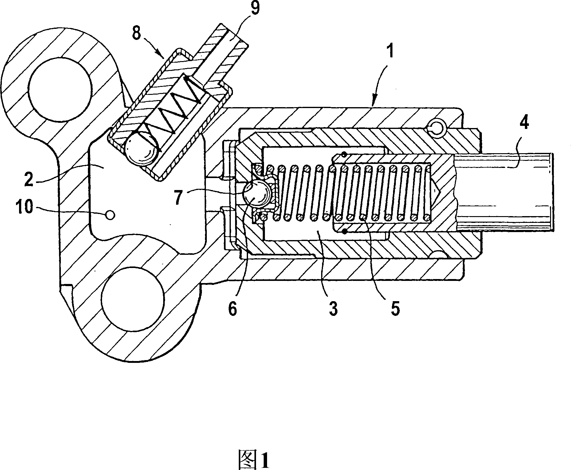
[0011] Arranged in the chain tensioner housing 1 is an oil supply chamber 2 , which is connected to a high-pressure chamber 3 and in which a chain tensioner piston 4 is additionally pretensioned via a helical compression spring 5 . When the chain tensioner piston 4 springs in due to the increased tension in the chain drive, the oil in the high-pressure chamber 3 is primarily used as a factor for the springing in, since the spring 5 is not strong enough for this. The flow of oil from the high pressure chamber 3 into the oil supply chamber 2 is prevented by the ball valve 6 and the valve seat 7 . According to the invention, the oil supply chamber has an overpressure valve 8, which passes through the wall of the oil supply chamber 2 and has an oil hole 9 formed as an oil nozzle, which is arranged in such a way that it serves to lubricate a chain not shown , the chain is hydraulically tensioned by chain tensioner piston 4.

[0012] 10 in the accompanying drawings represents the t...


PUM


Abstract

A hydraulic chain adjuster wherein a high-pressure chamber (3), which receives chain adjuster piston (4) that is mounted counter to a spring, is connected to an oil supply chamber (2) of the adjuster, which is connected to the oil gallery of the motor. An over-pressure valve (8) is incorporated into the oil supply to the chain adjuster, particularly inside the wall of the oil supply chamber (2). The opening pressure of said valve is adapted to the desired supply pressure of the adjuster.

Description

technical field [0001] The invention relates to a hydraulic chain tensioner, the high-pressure chamber containing the piston of the chain tensioner supported by the reverse spring is connected with the oil supply chamber of the tensioner, and the oil supply chamber is connected with the oil circuit of the engine. Background technique [0002] The sometimes high oil supply pressure supplied by the chain tensioner, especially with a cold engine or high rpm, affects the chain tensioner piston and leads to an increased pretension of the chain tensioner piston and thus to an average higher chain force. This not only increases the friction on the transmission and adversely affects the noise conditions, but also worsens the wear conditions. [0003] With the increase of chain patterns, these existing problems are more prominent. Among them, it is particularly worthy of attention that the additional length of the chain will be increased. [0004] Although it has been proposed to l...

Claims


Application Information

Patent Timeline
Patent Type & Authority Applications(China)
IPC IPC(8): F16H7/08
CPCF16H2007/0859F16H2007/0814F16H2007/0812F16H2007/0806F16H7/0848F16H7/08
Inventor 托马斯·乌莱因
Owner SCHAEFFLER KG
Why Eureka
Try Eureka