Flapping wing unit of flapping wing aircraft

A flying machine and wing handle technology, applied in the field of flapping wing devices, can solve the problems of unstable flying state, small buoyancy, and large buoyancy changes of the flapping wing flying machine

Inactive Publication Date: 2007-08-22
李玺芳
View PDF0 Cites 45 Cited by
  • Summary
  • Abstract
  • Description
  • Claims
  • Application Information

AI Technical Summary

Problems solved by technology

However, the flying wings of the orthopter simply flap up and down, resulting in little buoy

Method used


Image

  • Flapping wing unit of flapping wing aircraft

Examples


Embodiment Construction

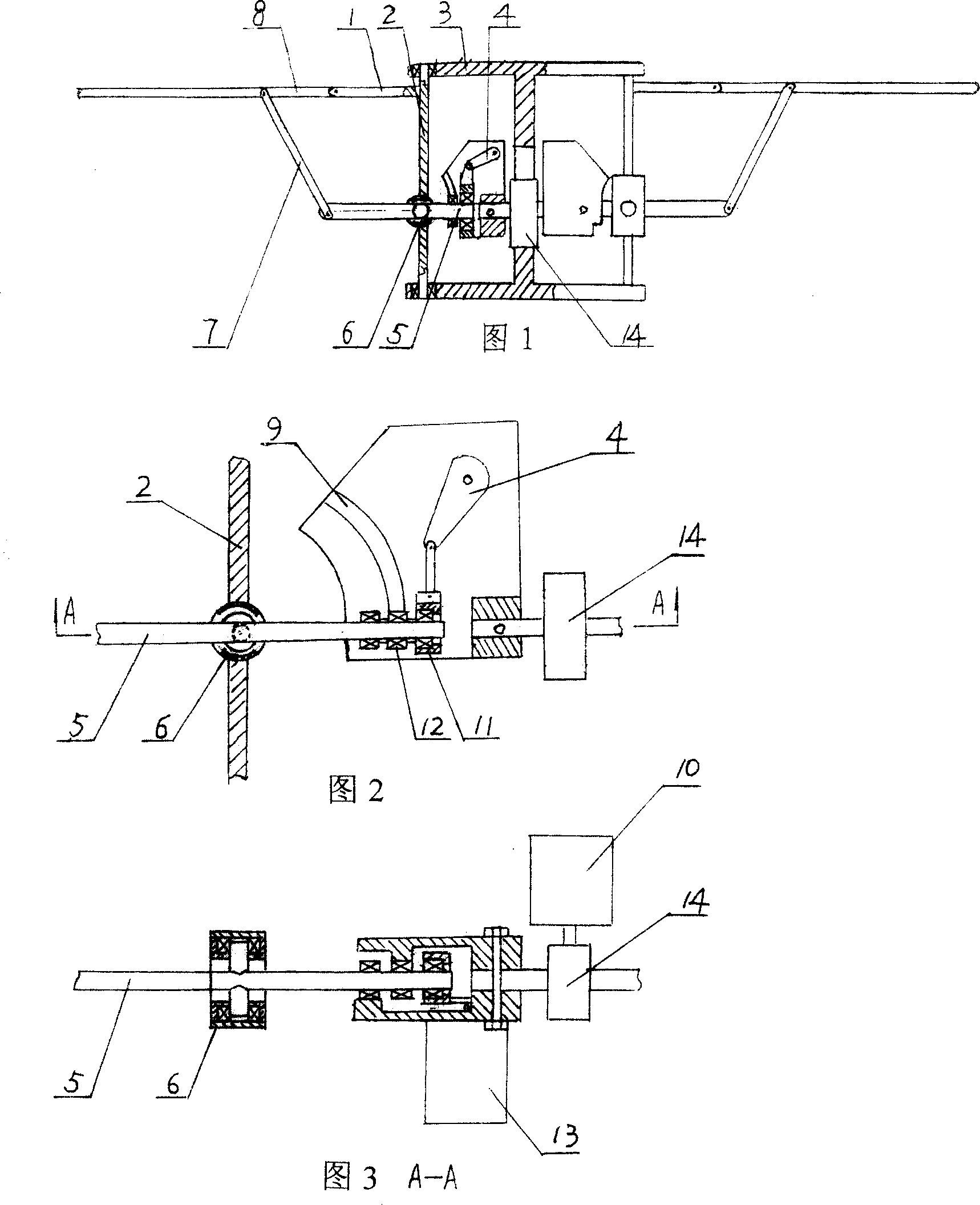
[0010] A flapping wing device of a flapping wing aircraft, as shown in Figure 1, Figure 2, and Figure 3, includes a wing handle 8 connected to the wing, and a motor 10 installed on the base is respectively connected to two symmetrical steering gear drive. The motor 13 of the steering gear driving device is hinged to the bearing seat 11 installed at the end of the lever transmission shaft 5 through the crank linkage mechanism 4, and the roller 12 installed on the lever transmission shaft 5 cooperates with the slideway 9 in the steering gear housing, and the slideway 9 is an outwardly convex or inwardly concave arc-shaped track. The bearing seat 6 matched with the lateral symmetrical support shaft affixed to the middle part of the lever transmission shaft 5 is arranged on the rotating shaft 2, and the two ends of the rotating shaft 2 are installed on the casing 3 through bearings. The bearing seat 6 is a cylindrical bearing seat, and the middle part of the cylinder is provided ...


PUM


Abstract

The present invention relates to flapping wing aircraft, and is especially an improved flapping wing unit of flapping wing aircraft. The motors on the base respectively drive the two symmetrical steering engine drivers to rotated through a speed reducer, the motor of the steering engine driver is hinged through crank-link rod mechanism to lever driving shaft with a first bearing seat in the end, the roll on the lever driving shaft is fitted to the slipway inside the shell of the steering engine driver, the rotation shaft with bearings and second bearing seats is mounted on the casing, the lever driving shaft has the other end hinged to link rod hinged to wing handle, and the wing handle has one end with mounted wing and the other end hinged to the support arm of the rotation shaft. The present invention makes the flapping wing aircraft possess great lifting power, propelling power and stable flying state.

Description

technical field [0001] The invention belongs to the improvement of the flapping wing structure of the flapping wing aircraft, in particular to the flapping wing device of the flapping wing aircraft. Background technique [0002] In the field of model aircraft, there is a kind of orthopter whose flight structure design is that the skeleton of the wing of the orthopter is fixed with the wing surface made of soft material, the motor drives the lever arm through the crank connecting rod, and the lever arm is fixed to the flying wing, so that the flying The wings flap up and down, creating air buoyancy that allows the orthopter to fly. However, the flying wings of the orthopter simply flap up and down, resulting in little buoyancy and large buoyancy changes, which makes the flight state of the orthopter very unstable. Contents of the invention [0003] The object of the present invention is to provide a flapping wing device of a flapping-wing aircraft, which can make the flapp...

Claims


Application Information

Patent Timeline
IPC IPC(8): B64C33/02A63H27/28
Inventor 田顺强
Owner 李玺芳
Why Eureka
Try Eureka