Wide band rader utilizing multi-transmitting and multi-receiving frequency division signal and imaging method thereof

A multi-transmit and multi-receive, broadband radar technology, applied in the field of radar, can solve problems such as poor quality, achieve the effect of low performance requirements, easy to implement, and overcome poor imaging quality

Inactive Publication Date: 2007-08-22
TSINGHUA UNIV
View PDF0 Cites 86 Cited by
  • Summary
  • Abstract
  • Description
  • Claims
  • Application Information

AI Technical Summary

Problems solved by technology

[0006] The purpose of the present invention is to combine the idea of ​​multi-transmitting and multi-receiving frequency-division signals with broadband imaging radar, increase the repetition frequency of th

Method used


Image

  • Wide band rader utilizing multi-transmitting and multi-receiving frequency division signal and imaging method thereof
  • Wide band rader utilizing multi-transmitting and multi-receiving frequency division signal and imaging method thereof
  • Wide band rader utilizing multi-transmitting and multi-receiving frequency division signal and imaging method thereof

Examples


Example Embodiment

[0040] Example 1

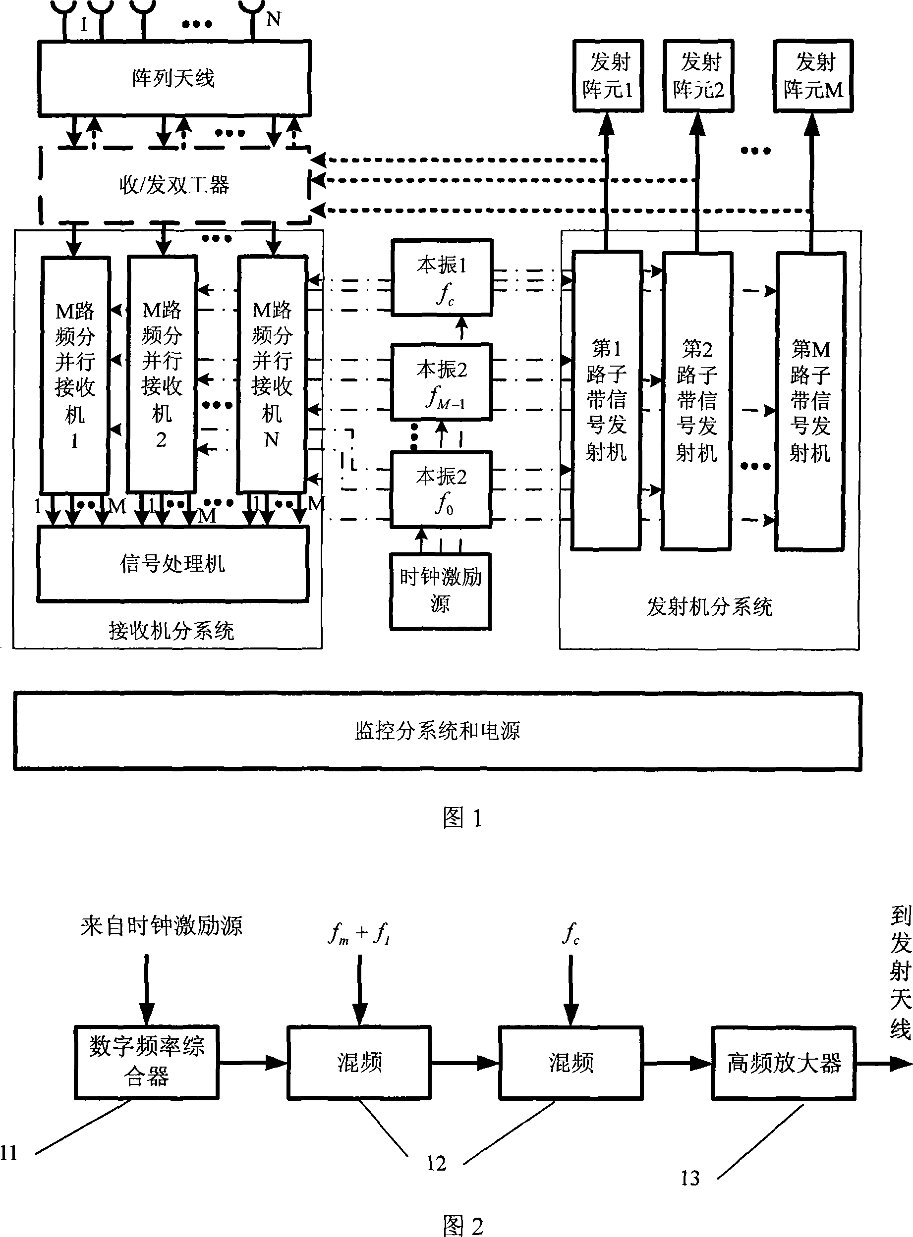
[0041]Figure 1 shows a block diagram of a wideband radar system using multiple transmitters and multiple receivers. The radar system of this embodiment is mainly composed of a transmitting / receiving array antenna, a transmitter sub-system, a receiver sub-system, a clock source, a monitoring sub-system, and a power supply. The transmitter sub-system of this embodiment includes M parallel sub-transmitters, which generate M channels of frequency division signals. The receiver sub-system includes N parallel sub-receivers and signal processors, and the sub-receivers are M channels. Frequency division parallel receiver. The components of the radar system of this embodiment are described as follows:

[0042] ①Transmitting / receiving array antenna: The receiving antenna and the transmitting antenna can share a set of array antennas. At this time, as shown by the dotted line in Figure 1, each extension of the receiver and each extension of the transmitter are connected to...


PUM


Abstract

The invention relates to a wide-band radar figure method used the multi-emitter and multi-receiver frequency molecular signal. It includes the below process: 1. the M array unit of the radar emitter emit M frequency molecular band signal; 2. the radar receiver is made up of N receiving array units which is set with M receiving channels matched to the M frequency molecular band signal, so it can get M*N channels of the echo signal; 3. disposing the M*N channels of the echo signal and finishing the object detection then it composes the many echoes into the high resolution figure in the object location and the distance. The invention has decreased the need of the radar to the instantaneous bandwidth; also the radar has the ability of the electronic scanning to complete the object detecting, tracking and figure.

Description

technical field [0001] The invention belongs to the technical field of radar, in particular, the invention relates to a broadband radar and an imaging method thereof. Background technique [0002] With the development of radar imaging technology, such as synthetic aperture radar (SAR), inverse synthetic aperture radar (ISAR), and radar identification technology, the distance resolution required by radar is getting higher and higher, so the required radar signal bandwidth is getting higher and higher. bigger and bigger. How to realize the transmission and reception of broadband signals has always been a difficult point in radar system design, and it is also a standard to distinguish many radar working systems. According to different broadband signal generation and signal processing methods, the methods for obtaining broadband signals and high-resolution one-dimensional range images can be divided into three categories: the imaging method using the step frequency hopping syst...

Claims


Application Information

Patent Timeline
IPC IPC(8): G01S13/00G01S7/02G01S7/282G01S7/285H04B7/04
Inventor 许稼彭应宁戴喜增王秀坛叶春茂许嘉
Owner TSINGHUA UNIV
Why Eureka
Try Eureka