Gradual damping oil buffer

A technology of buffer and damping oil, applied in contact vibration/shock damping, liquid shock absorber, high-voltage air circuit breaker, etc., can solve problems such as unreasonable distribution of braking force of oil buffer, achieve smooth return flow and fast speed Effect

Inactive Publication Date: 2007-08-22
浙江开关厂有限公司
View PDF0 Cites 35 Cited by
  • Summary
  • Abstract
  • Description
  • Claims
  • Application Information

AI Technical Summary

Problems solved by technology

[0008] The technical problem to be solved by the present invention is that the distribution of braking force of the oil buffer in the circuit breaker is unreasonable, and a gradual damping oil buffer matching the opening process of the switchgear is provided

Method used


Image

  • Gradual damping oil buffer
  • Gradual damping oil buffer
  • Gradual damping oil buffer

Examples


Embodiment 1

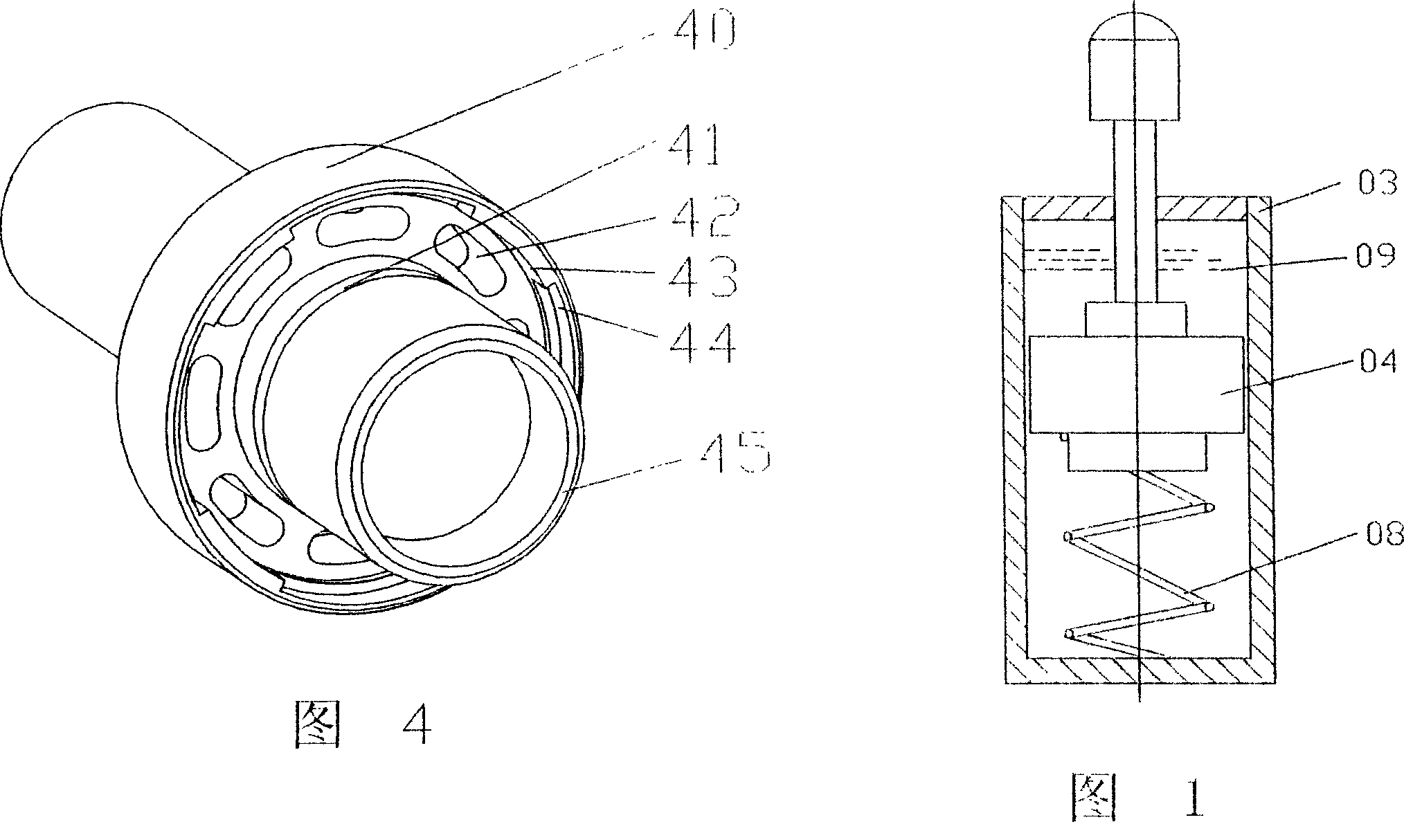
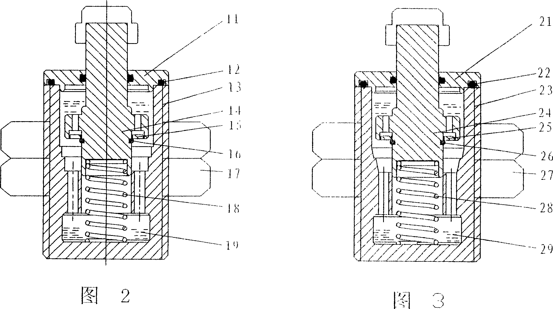
[0028] See Figure 2, Figure 4, Figure 5. In this embodiment, the oil buffer includes an end cover 11, a sealing ring 12, an oil cylinder 13, a piston 14, an annular stop ring 15, and a stopper 16 to form a piston assembly. The fixing nut 17 fixes the oil buffer on the vacuum circuit breaker, and the piston A stage clip 18 is connected to the bottom, and buffer oil 19 is filled in the oil cylinder; the end cover 11 and the sealing ring 12 seal the buffer oil in the cavity of the oil cylinder 13 .

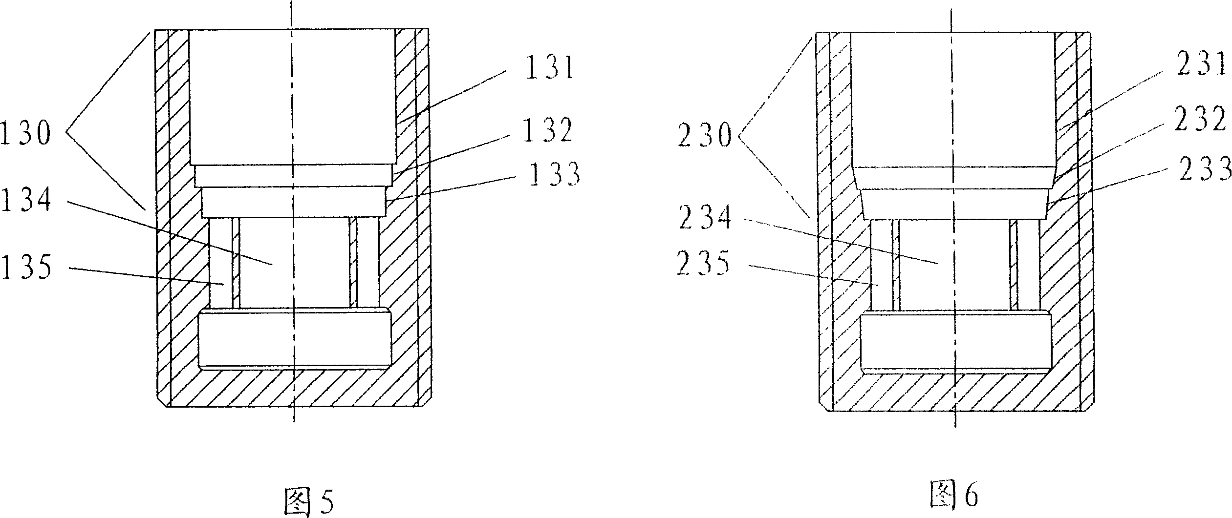
[0029] There is a working area 130 and a guide hole 134 in the oil cylinder 13, wherein the inner wall of the working area 130 is composed of several sections of cylindrical surfaces 131, 132, 133, with rounded corners smoothly transitioning between each section. The inner diameter gradually becomes smaller; several oil holes 135 are distributed around the periphery of the guide hole 134 .

[0030] The piston 14 is a multi-section cylinder, the lower section is a guide cylinder 45, ...

Embodiment 2

[0033] See Figure 3, Figure 4, Figure 6. In this embodiment, the oil buffer includes an end cover 21, a sealing ring 22, an oil cylinder 23, a piston 24, an annular stop ring 25, and a stopper 26 to form a piston assembly. The fixing nut 27 fixes the oil buffer on the vacuum circuit breaker, and the piston The bottom is connected with stage clip 28, and buffer oil 29 is filled in the oil cylinder;

[0034] There is a working area 230 and a guide hole 234 in the oil cylinder 23. The inner wall of the working area 230 can also be divided into three sections 231, 232, and 233, wherein both sections 232 and 233 are in the shape of a truncated cone, and the inner diameter of the oil cylinder gradually decreases from top to bottom; A plurality of oil passing holes 235 are distributed around the periphery of the guide hole 234 .

[0035] The piston 24 is a multi-section cylinder, the lower section is a guide cylinder 45, and the middle section is a piston main body 40 (the piston in...


PUM


Abstract

This invention discloses a tapered damp oil buffer used in a vacuum breaker including an oil cylinder, an end cover, a sealed coil, a piston component and a spreader spring, in which, the piston component and the spreader spring are set in the oil cylinder including a working region and a guide hole filled with buffer oil and sealed with an end cover and a sealing loop characterizing that: the clearance between the piston and the oil cylinder working region is a variable value, and the clearance is large in the prophase of the movement of the piston and the clearance is small in the latter perion of the movement, and the distribution of the brake of the oil buffer is matched to the braking process of a switch device.

Description

technical field [0001] The invention belongs to the field of electrical switches, and more specifically relates to a buffer in a vacuum circuit breaker, especially a gradual damping oil buffer. Background technique [0002] Among medium voltage circuit breakers currently in use, vacuum circuit breakers occupy a large proportion. The stroke of the vacuum circuit breaker is small, but its opening speed is very high. In order to stop a moving part with a high speed within a short stroke, a buffer is generally used to absorb the kinetic energy of the moving part, and the moving part should not rebound significantly at the end of the stroke. The importance of buffers in vacuum circuit breakers is often overlooked, but in fact its role is extremely important. At present, oil buffers are generally used in domestic vacuum circuit breakers, and the structure is similar. They are all equipped with pistons in the oil cylinders. There is a certain amount of buffer oil in the oil cylin...

Claims


Application Information

Patent Timeline
Patent Type & Authority Applications(China)
IPC IPC(8): H01H3/60H01H33/666F16F9/10
Inventor 俞慧忠周庆清苏伟民汪家养
Owner 浙江开关厂有限公司
Why Eureka
Try Eureka