
Heald frame bending mode control device

A technology of bending mode and control device, applied in the direction of heald, non-rotation vibration suppression, textile, etc., can solve the problems of reducing vibration and ineffectiveness, reducing the weight of the heald frame, reducing the wall thickness of the beam, and improving the dynamic working conditions Effect

Inactive Publication Date: 2013-10-09
JIANGSU WANGONG TECH GRP CO LTD
View PDF10 Cites 3 Cited by
  • Summary
  • Abstract
  • Description
  • Claims
  • Application Information

AI Technical Summary

Problems solved by technology

In the past, only foam was placed in the inner cavity of the beam, and the foam had no effect on reducing vibration

Method used


Image

  • Heald frame bending mode control device
  • Heald frame bending mode control device
  • Heald frame bending mode control device

Examples


Embodiment 1

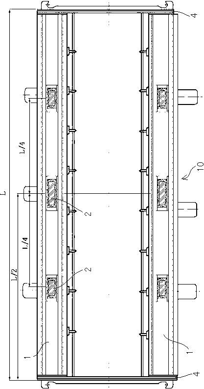
[0031] refer to figure 1 As shown, the main structure of the heald frame 10 is composed of two upper and lower beams 1 and two left and right side rails 4 . Most of the beams 1 are made of aluminum alloy flat tubes, and the two ends of the upper and lower beams 1 are connected by two side rails 4, and the side rails 4 are made of stainless steel or aluminum. The heald frames 10 are 10-14 mm thick, and two adjacent pages of the heald frames 10 are separated by wooden boards to alleviate the collision between the heald frames.

[0032] Fix the acceleration sensor that measures the response signal on a point of the heald frame 10, hit each node on the heald frame 10 with an impact hammer in turn, and collect and calculate the two sets of signals at the same time to obtain a row of the transfer function matrix, Change the fixed points of the accelerometer one by one, and repeat the above measurement, which obtains all the information of the transfer function matrix. Curve fittin...

Embodiment 2

[0045] refer to Figure 7 As shown, the difference from Embodiment 1 is that: the inner walls on both sides of the beam 1 are axially provided with a pair of upper and lower bosses 102, the vibration absorber 2 is embedded in the bosses 102, and the vibration absorber 2 is embedded in the bosses 102. The device 2 is positioned axially through two positioning pins 3 at both ends.

Embodiment 3

[0047] refer to Figure 8 As shown, the difference from Embodiment 1 is that transition fit is adopted between the inner wall of the vibration absorber 2 and the outer tube 1 .


PUM


Abstract

The invention discloses a heald frame bending mode control device, which is composed of vibration absorbers in beams. Each beam is internally provided with three vibration absorbers, wherein one vibration absorber is arranged at the middle part of the beam, the other two vibration absorbers are arranged at the two sides of the beam, and the distance from each of the vibration absorbers at two sides to the center of the beam is a quarter of L which is the total length of the beam. Each vibration absorber comprises a hollow outer tube with a rectangular transverse section. Both ends of each outer tube are covered with shock insulators. A mass block corresponding to the length of the outer tube is arranged in each outer tube, and is connected to the corresponding shock insulators through copper sheet springs at both ends, so that the mass block can be hung in the corresponding outer tube to form a cavity which is filled with elastic high polymer materials. As the vibration absorbers are arranged in the inner cavities of the heald frame beams, vibration is alleviated, and the wall thickness of the beam is reduced so as to lighten the weight of a heald frame and improve the dynamic operating conditions of the heald frame.

Description

technical field [0001] The invention relates to the field of looms, in particular to a bending mode control device of a heald frame. Background technique [0002] In the opening mechanism, the heald frame reciprocates, and the beam has a stationary stage at the lowest and highest positions. After the lift or drop, the heald frame beam vibrates violently. The heald frame is a flat frame type part. The main vibration of the heald frame is not in the moving direction, but strongly vibrates in the flat and thin direction of the heald frame, and the strong vibration direction is perpendicular to the moving direction. The low-cost vibration of the heald frame is the first-order and second-order bending modes, and the low-cost vibration frequency overlaps with the operating frequency of the loom. [0003] The working conditions of the heald frame are very poor, the heald frame vibrates greatly at low frequency, and the middle of the beam can bend up to 5 mm. The running speed of ...

Claims


Application Information

Patent Timeline
IPC IPC(8): D03C9/06F16F15/04F16F7/00
Inventor 周平祝章琛
Owner JIANGSU WANGONG TECH GRP CO LTD
Learn More