Multi-Mode Control Station, Radio Communication System, Radio Station, and Radio Communication Control Method

a control station and radio communication technology, applied in the field of multi-mode control stations, wireless communication systems, wireless communication control methods, etc., can solve problems such as difficult communication in equipments conforming to different standards, and achieve the effect of improving the overall system throughpu

Inactive Publication Date: 2008-08-21
KOHNO RYUJI +1
View PDF10 Cites 102 Cited by
  • Summary
  • Abstract
  • Description
  • Claims
  • Application Information

AI Technical Summary

Benefits of technology

[0025]According to the present invention, under an environment where a plurality of types of wireless communication schemes are mixed and used within an area in close proximity, various parameters for communication links between the terminal stations and the multimode control terminal station, or for between terminal stations are collected, and resources such as the communication scheme, transmission speed and time allocation rate used at the communication link are allocated in such a manner that total throughput of traffic in the network becomes maximum and the interference the wireless stations are subjected to is reduced, so that it is possible to improve overall system throughput.

Problems solved by technology

Such wireless communication schemes can eliminate the inconvenience of cable wiring because connection between equipments are established wirelessly, but communication is difficult in equipments conforming to different standards due to different communication schemes including, for example, a modulation method, codec, and protocol.

Method used


Image

  • Multi-Mode Control Station, Radio Communication System, Radio Station, and Radio Communication Control Method
  • Multi-Mode Control Station, Radio Communication System, Radio Station, and Radio Communication Control Method
  • Multi-Mode Control Station, Radio Communication System, Radio Station, and Radio Communication Control Method

Examples


embodiment 1

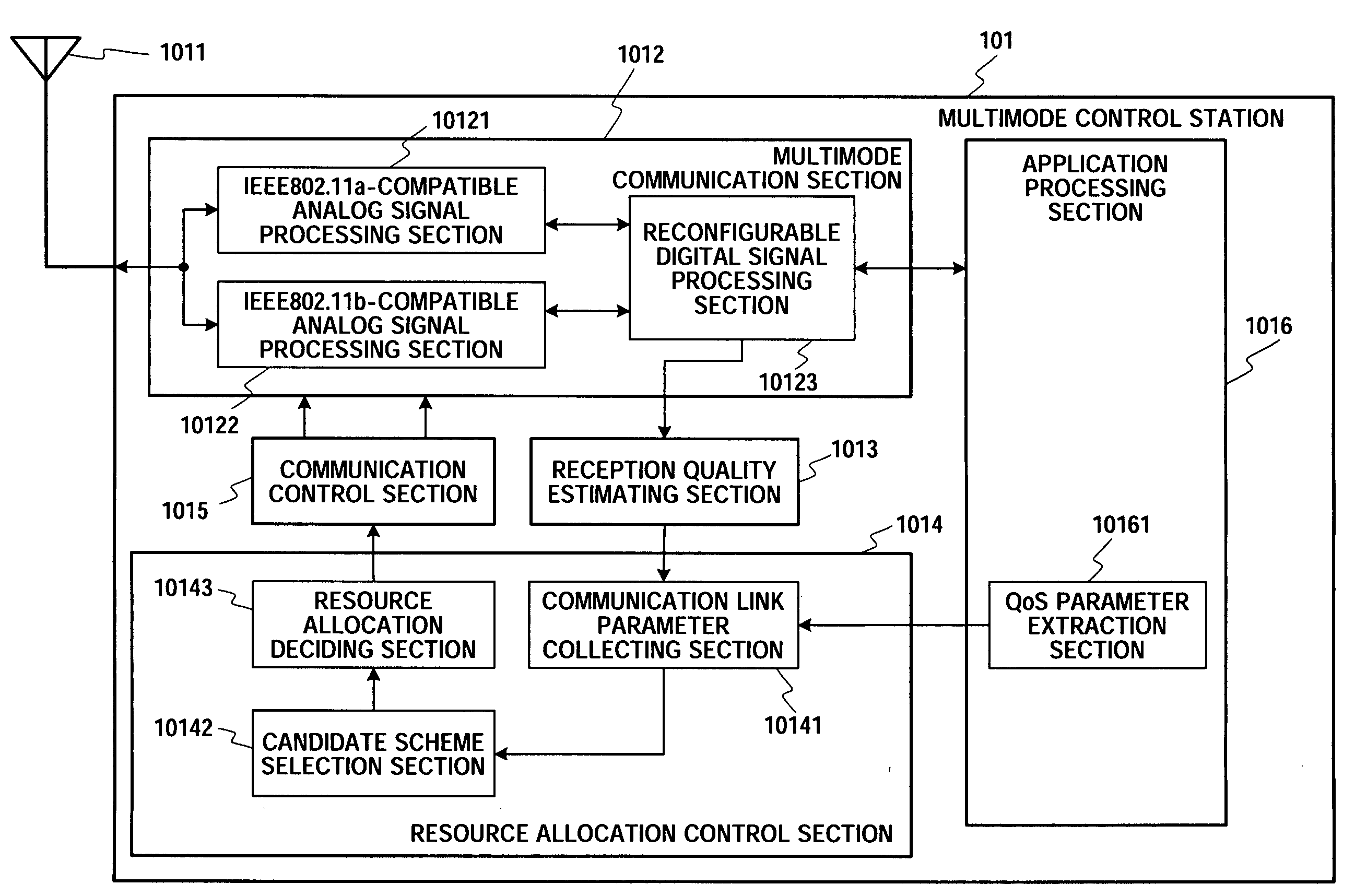
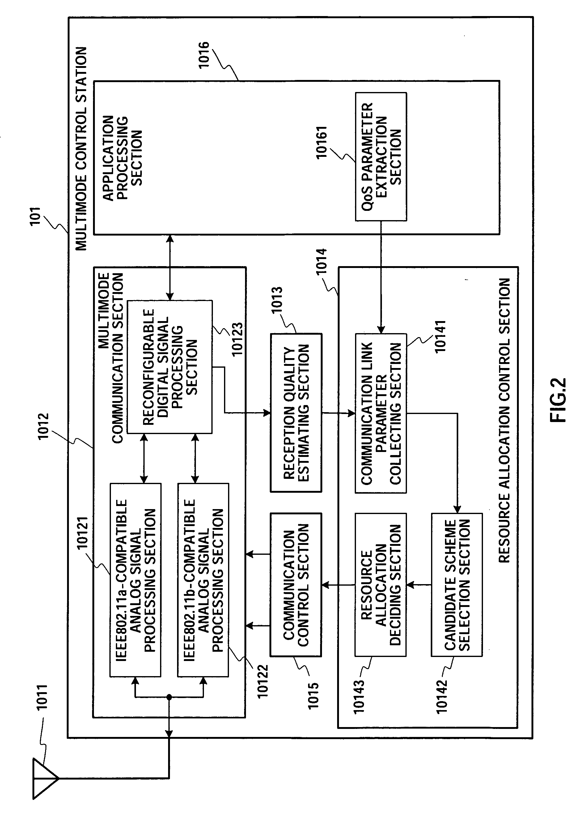
[0064]In this embodiment, it is proposed that a control station collects information such as communication quality and QoS (Quality of Service) of transmitted data at communication links with the terminal stations under an environment where a network is formed in a situation where wireless communication schemes based on a plurality of wireless communication standards are mixed between the control station and the plurality of terminal stations, in a comparatively confined space, decides communication resources allocated to the communication links based on this collected information and carries out communication.

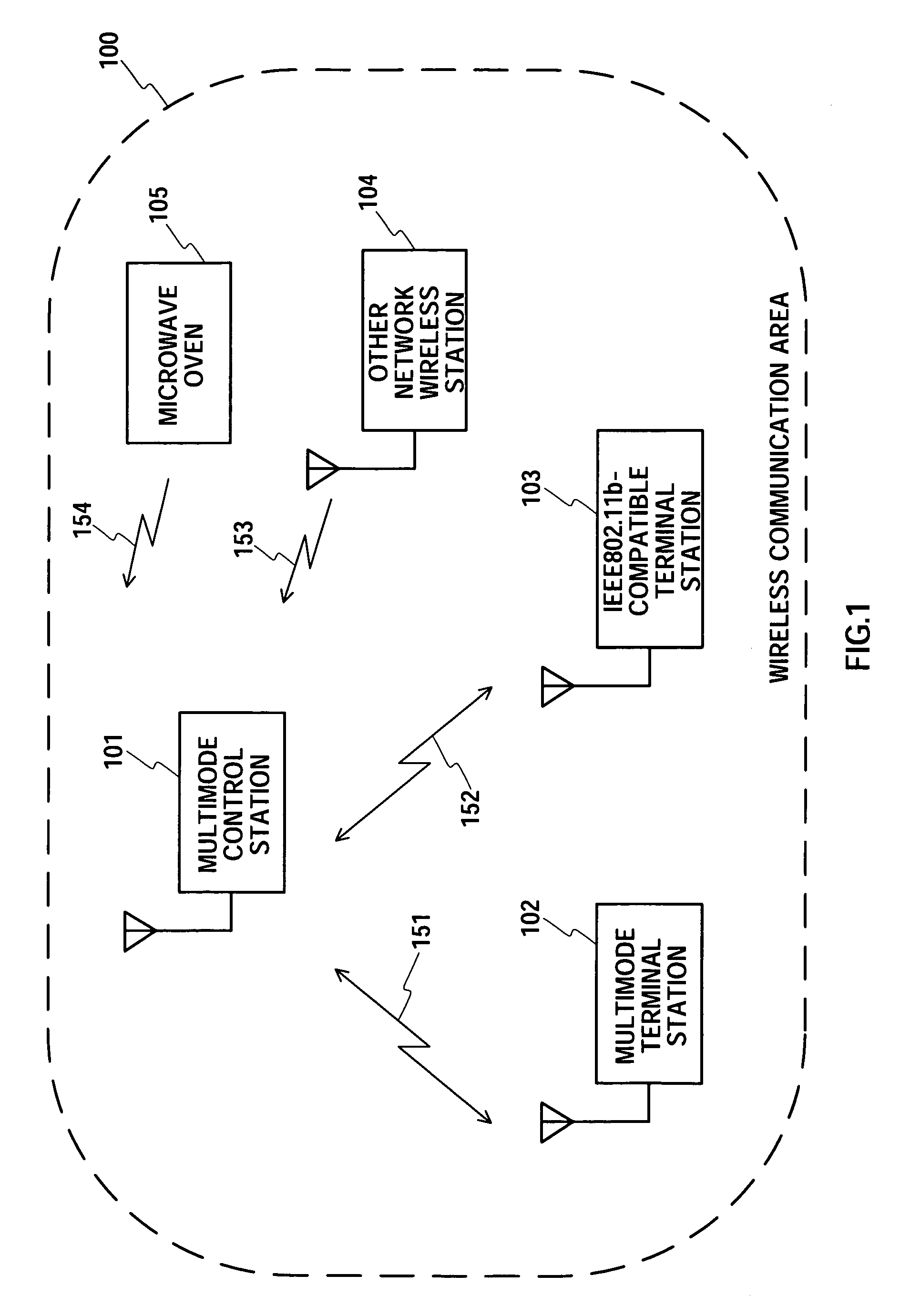
[0065]FIG. 1 shows wireless stations and interference sources existing within the wireless communication area used for the description of this embodiment. Wireless communication area 100 shows a spatial range where multimode control station 101 is able to communicate by constructing a network using wireless communication. Specifically, an area assumed to be an area that is com...

embodiment 2

[0215]In this embodiment, an embodiment relating to communication control will be described where the number of terminal stations for which data transmission is carried out within a network changes while controlling communication so that a communication throughput value in a network of the embodiment 1 is maximized, and communication schemes used at the communication links between a multimode control station and a plurality of multimode terminal stations are dynamically switched. The configuration of the network is fundamentally the same as shown in FIG. 1 in the embodiment 1 or that further typified in FIG. 37. A difference from the embodiment 1 is control content in communication time allocation of control section 11 at multimode control station 10, and this control content will be described in the following.

[0216]FIG. 15 shows a flowchart for control when carrying out control of communication time allocation at control section 11 of this embodiment. In this embodiment, the total ...

embodiment 3

[0257]In this embodiment, a multimode control station that decides communication resource allocation used at wireless communication links between the wireless stations within an area where a plurality of types of wireless communication schemes collects communication link information reported from the wireless stations within a wireless control area and presents collectively managing the communication link information. As a result, the multimode control station is able to understand how to receive and cause interference between wireless terminals within the management area, so that it is possible to decide communication resources to be allocated to the wireless terminal stations so that overall communication of the management area is optimized.

(1) Overall Configuration of Wireless Communication System

[0258]An overall configuration of a wireless communication system of the embodiment 3 of the present invention is shown in FIG. 17. In FIG. 17, 201 to 204 denote wireless stations, 205 d...


PUM


Abstract

The overall throughput of the radio communication traffic in a radio communication area in a radio communication environment where a plurality of types of radio communication systems are mixedly used in a neighboring radio communication area is improved. When a multi-mode control station (101) performs communication with a terminal station in a network through a plurality of types of communication systems, a communication link parameter collecting section (10141) collects parameters indicating the states of the communication links. A resource allocation determining section (10143) determines communication resource allocation for which the throughput is the greatest for each resource allocation period according to the parameters. A communication control section (1015) controls a multi-mode communication unit (1012) according to the result of the determination.

Description

TECHNICAL FIELD [0001]The present invention relates to a multimode control station, wireless communication system, wireless station, and wireless communication control method, and particularly relates to technology for improving total throughput of communication traffic in an environment where a plurality of communication links for wireless stations by means of a plurality of types of wireless communication schemes are mixed and used within an area in close proximity.BACKGROUND ART [0002]In recent years, near-field wireless communication schemes utilized within a room such as an office or a household have come to prominence, with services and products using wireless communication schemes such as those conforming to IEEE802.11b and IEEE802.11b.11g that are wireless LAN (Local Area Network) standards and the Bluetooth (registered trademark) standard targeting connection between various equipment such as computers and mobile terminal stations etc. already having been implemented. Such ...

Claims


Application Information

Patent Timeline
Patent Type & Authority Applications(United States)
IPC IPC(8): H04B7/005H04B15/00H04Q7/20H04L12/28H04W16/14
CPCH04W16/14H04W88/06H04W72/04
Inventor ABE, KATSUAKISAKAMOTO, TAKENORIMATSUOKA, AKIHIKOKOHNO, RYUJITANIGUCHI, MOTOKO
Owner KOHNO RYUJI
Why Eureka
Try Eureka