Fan fixing device

A fan fixing device and fan technology, which are applied in the direction of electric solid device, cooling/ventilation/heating transformation, semiconductor/solid device components, etc., can solve the problem of inability to adjust the angle of electronic components to dissipate heat, etc.

Inactive Publication Date: 2007-08-22
HONG FU JIN PRECISION IND (SHENZHEN) CO LTD +1
View PDF0 Cites 3 Cited by
  • Summary
  • Abstract
  • Description
  • Claims
  • Application Information

AI Technical Summary

Problems solved by technology

However, when the fan is placed directly on the table, the fan will move due to its own vibration position, and the fan can only face the horizontal direction of the CPU (parallel to the table), and cannot adjust the angle to dissipate heat from other electronic components on the motherboard.

Method used


Image

  • Fan fixing device
  • Fan fixing device
  • Fan fixing device

Examples


Embodiment Construction

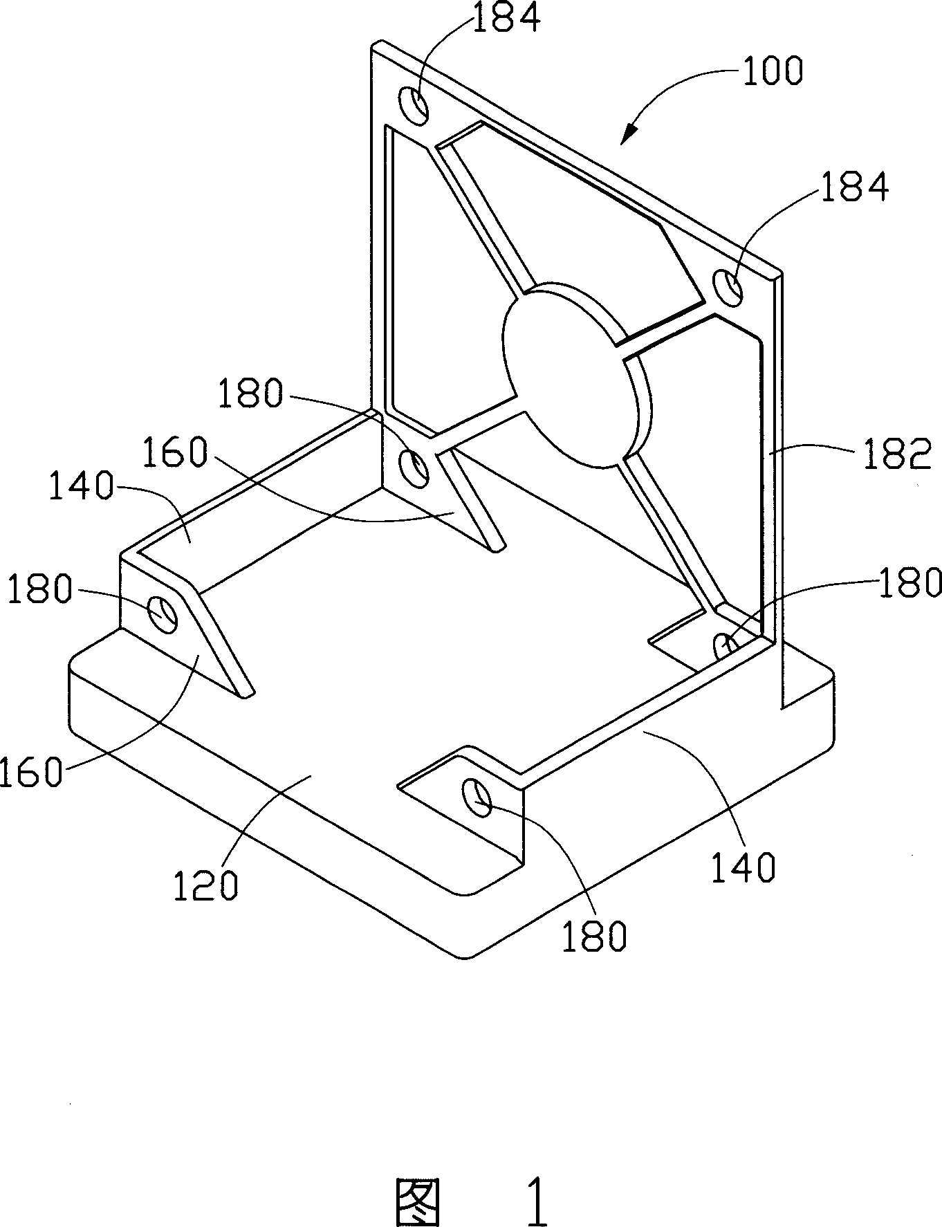
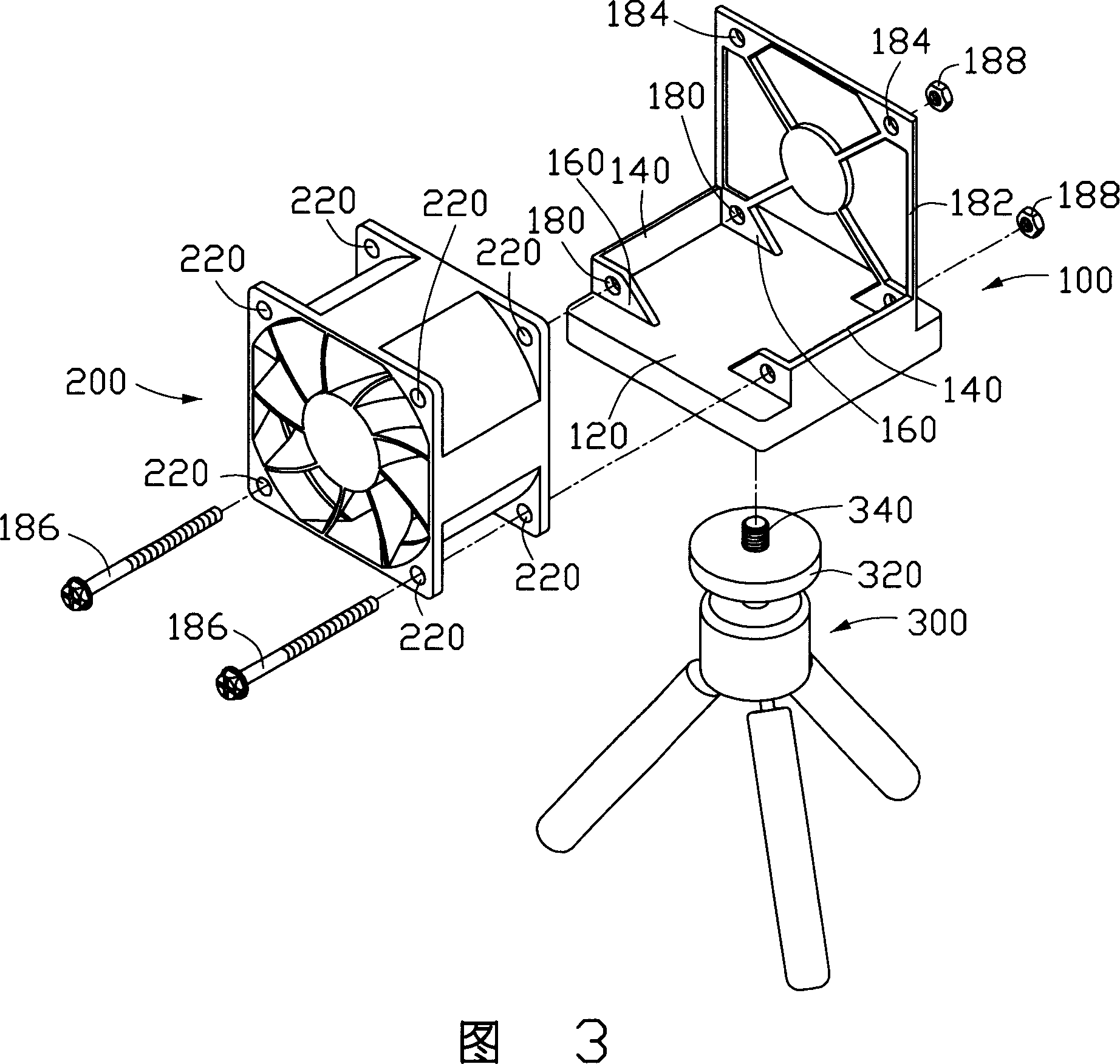
[0012] Please refer to FIG. 1 to FIG. 3 , the fan fixing device 100 of the present invention is used to fix a fan 200 on a stand 300, and a mounting hole 220 is respectively provided at the octagons of the fan 200, and the stand 300 includes a platform 320 , a stud 340 is pierced in the middle of the pan-tilt 320 , and the pan-tilt 320 cooperates with the stud 340 to rotate in the horizontal direction or deflect at various angles.

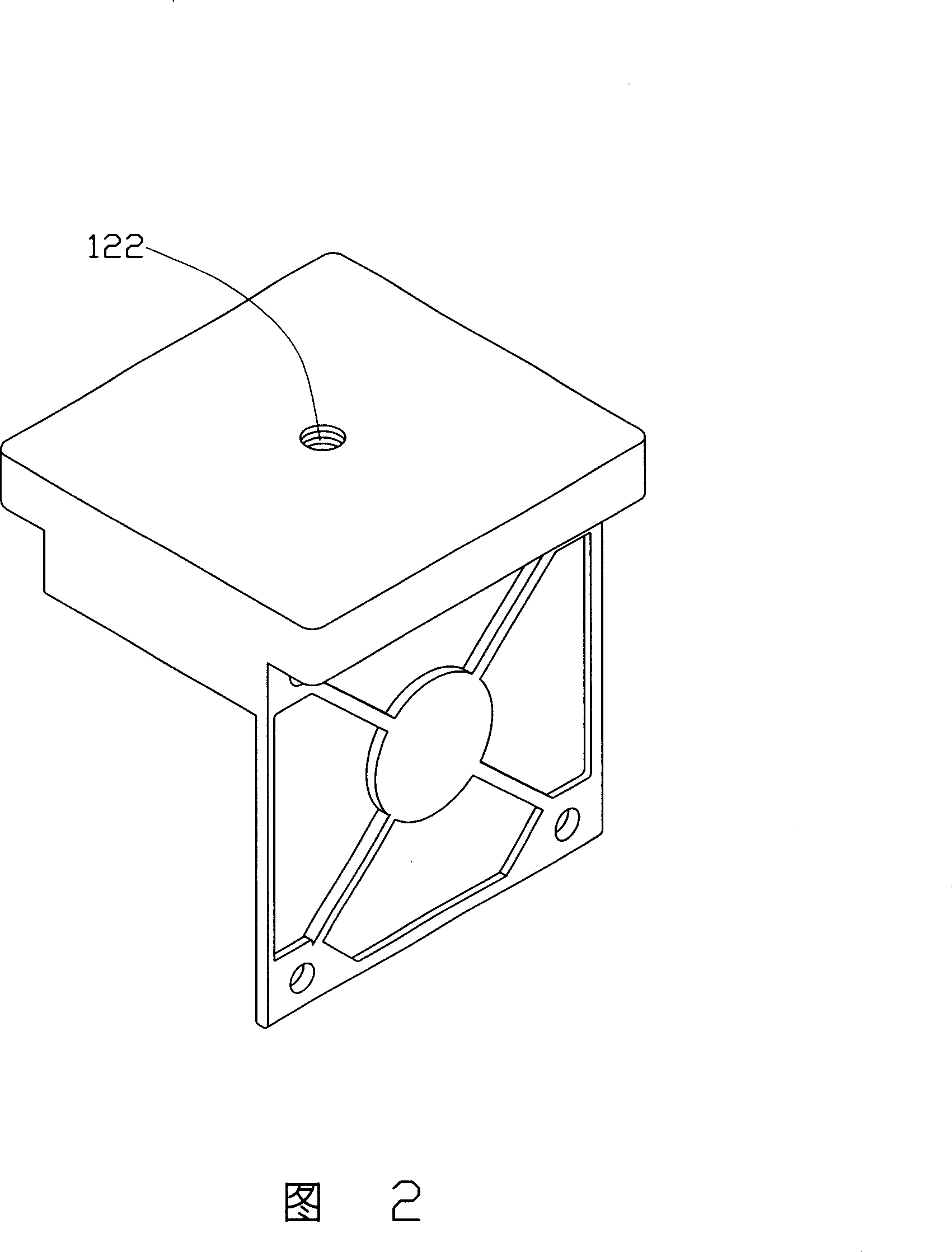
[0013] A preferred embodiment of the fan fixing device 100 of the present invention includes a body part 120 , and the body part 120 includes a fan fixing part and a stand fixing part. The fan fixing part is used to connect and fix the fan 200 , and the stand fixing part is used to connect and fix the stand 300 .

[0014] Wherein, the fan fixing member is two clamping parts 140 protruding along two sides of the body part 120, each clamping part 140 has two mutually parallel lugs 160, and each lug 160 corresponds to a The mounting holes 220 of the ...


PUM


Abstract

A fixture device of fan is prepared as fixing and connecting fan by fan fixing elements, fixing and connecting foot stool by foot stool fixing elements, fixing and connecting fan on fan fixture unit by fan fixing elements as well as fixing and connecting fan fixture unit on foot stool by foot stool fixing elements.

Description

【Technical field】 [0001] The invention relates to a fixing device, in particular to a fan fixing device for fixing a fan on a foot frame to facilitate position adjustment of the fan. 【Background technique】 [0002] With the rapid development of integrated circuit manufacturing technology, electronic components are moving towards faster computing speed. As the calculation speed of electronic components is getting faster and faster, electronic components will generate a lot of heat energy when they operate at high speed. If the heat energy generated by electronic components is not treated, the temperature of electronic components will continue to rise, which will affect the stability of their operation. In severe cases, electronic components will be burned. [0003] In the process of electronic testing, the object under test usually needs to dissipate heat to ensure its normal operation. Taking the motherboard as an example, the CPU (Central Processing Unit, central processin...

Claims


Application Information

Patent Timeline
Patent Type & Authority Applications(China)
IPC IPC(8): H05K7/20H01L23/40G06F1/20G12B15/04
Inventor 孙正衡
Owner HONG FU JIN PRECISION IND (SHENZHEN) CO LTD
Why Eureka
Try Eureka