
Heat exchanger with indentation pattern

A technology of heat exchangers and heat exchange plates, which is applied in the direction of heat exchange equipment, heat exchanger types, indirect heat exchangers, etc., and can solve problems such as high energy consumption

Active Publication Date: 2007-08-22
DANFOSS AS
View PDF0 Cites 16 Cited by
  • Summary
  • Abstract
  • Description
  • Claims
  • Application Information

AI Technical Summary

Problems solved by technology

Therefore, high pressure drop means high energy consumption

Method used


Image

  • Heat exchanger with indentation pattern
  • Heat exchanger with indentation pattern
  • Heat exchanger with indentation pattern

Examples


Embodiment Construction

[0016] Plate heat exchangers are well known devices for transferring heat between two different media. Plate heat exchangers are used in many different applications, and the invention is not limited to any particular application. The present invention is intended to apply to all brazed heat exchangers or heat exchangers assembled by other methods such as by welding, adhesives, or diffusion. The heat exchanger comprises a plate with an indented pattern and connections for the inlet and outlet of the two media. The plates are gathered in assemblies and joined together to form a complete device. The connection of the plates creates separate channels for the two media which circulate in countercurrent between the interleaved sets of plates. This technique is well known and thus will not be described in detail here.

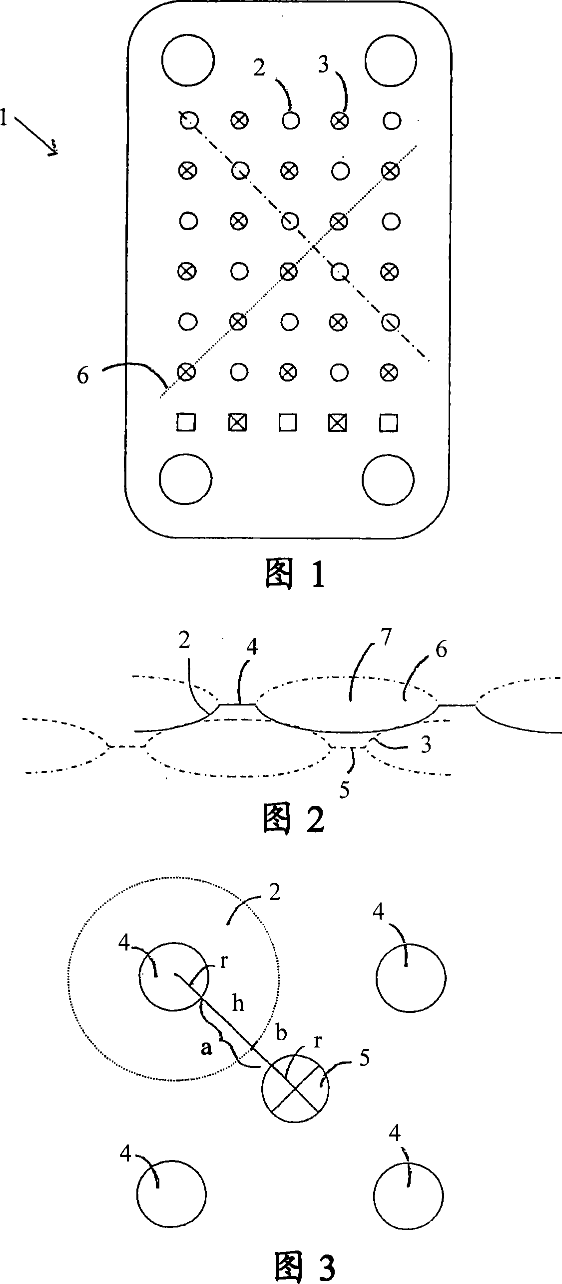
[0017] Fig. 1 is a plan view of an example of a heat exchange plate 1 according to the present invention. At the four corners are conventional connections for the...


PUM


Abstract

The invention relates to a heat exchanger with an indentation pattern, and specifically a heat exchanger with heat exchanger plates (1) provided with a special pattern instead of the traditional herringbone pattern. The pattern comprises at least one section with bulges (2) and hollows (3), said bulges and hollows having flat tops and bottoms intended to be placed against respective hollows and bulges of a heat exchanger plate of a corresponding design. The surface area of said tops and bottoms is such in relation to the distance between the tops and bottoms that channels (6) for the flow of a medium are formed between the bulges.

Description

technical field [0001] The present invention relates to a heat exchanger having a pattern of indentations, and more particularly to a heat exchange plate provided with a special pattern including bulges and dimples instead of the traditional herringbone pattern (hollow). Thanks to this new pattern, a stronger design and more favorable heat transfer characteristics can be achieved. Background technique [0002] Modern heat exchangers are often provided with plates having a so-called herringbone pattern (ie a pattern with indentations comprising straight peaks and valleys). The peaks and valleys change direction at the center, forming a pattern resembling a chevron. In the heat exchanger assembly, flip alternating plates so that the indentations cross each other. The heat exchanger can be fully brazed or provided with rubber gaskets. [0003] When this type of heat exchanger assembly is subjected to pressure and heat, the plates deform such that a bending moment is created...

Claims


Application Information

Patent Timeline
Patent Type & Authority Applications(China)
IPC IPC(8): F28F3/04F28F
CPCF28F3/04F28D9/0037
Inventor 拉尔斯·佩尔松
Owner DANFOSS AS
Learn More