Stage device

A technology of stage and stand, which is applied in the direction of feeding device, large fixed member, instrument, etc., can solve the problems of difficult transportation, stone and stone processing, etc., and achieve the effect of reducing the moving range, saving space and maintaining the plane accuracy

Inactive Publication Date: 2007-08-29
SUMITOMO HEAVY IND LTD
View PDF1 Cites 9 Cited by
  • Summary
  • Abstract
  • Description
  • Claims
  • Application Information

AI Technical Summary

Problems solved by technology

[0006] However, for example, when the size of a flat workpiece increases, the stage device must increase the suction area of ​​the suction pad that suctions the workpiece, so that the X stage and the stone table that support the suction pad also become larger. Furthermore, the problem of increasing the size of the entire device
[0007] Moreover, if the entire device continues to grow in size, there will be problems such as difficulty in securing stone materials and stone processing, and difficulty in transportation due to increased weight.

Method used


Image

  • Stage device
  • Stage device
  • Stage device

Examples


Embodiment 1

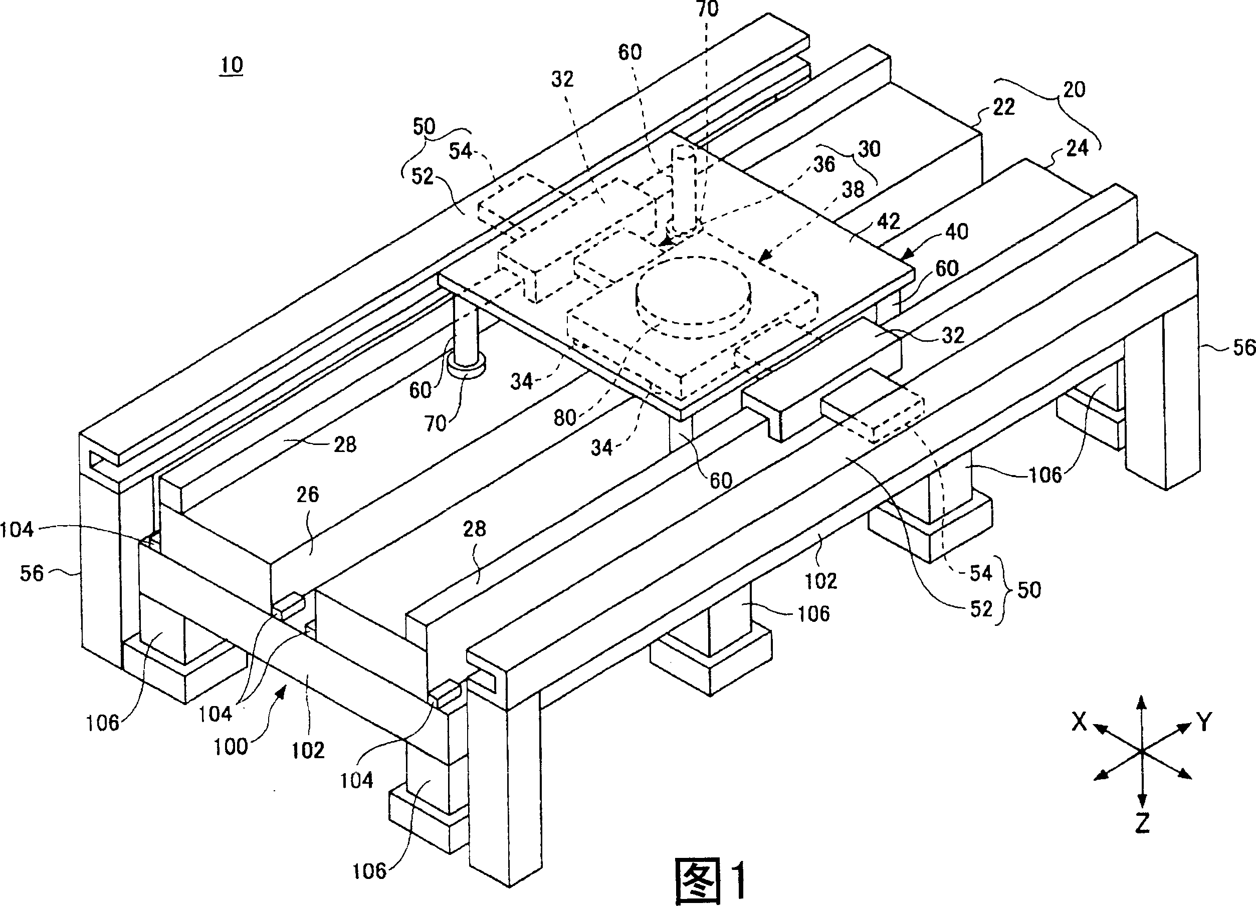
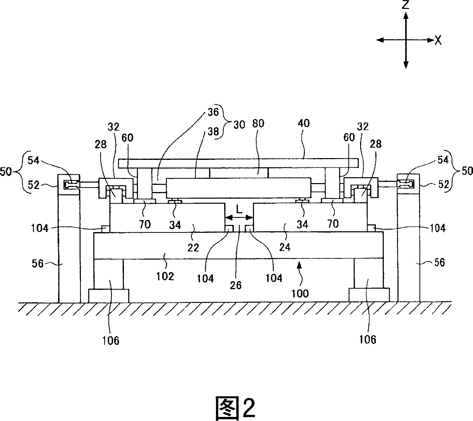
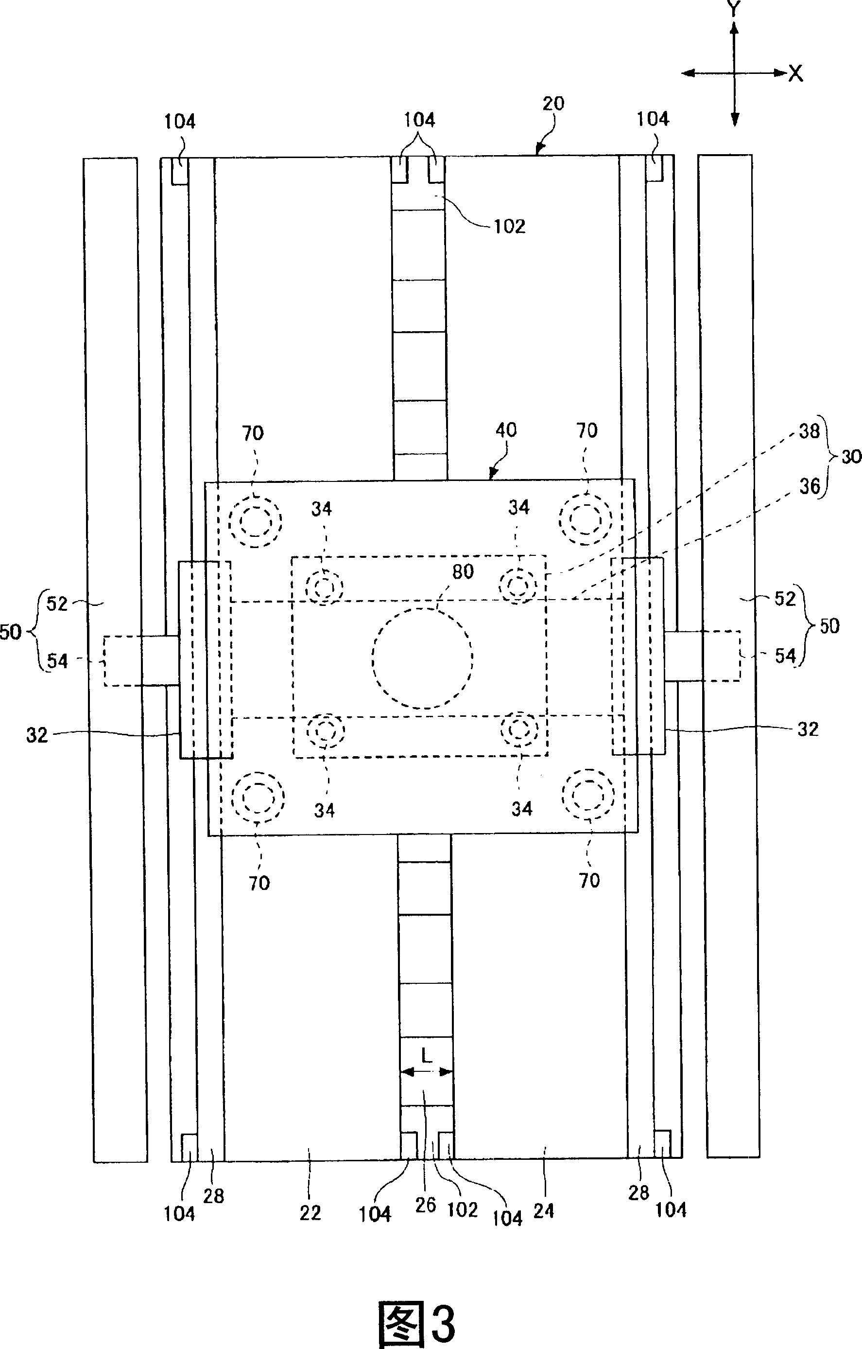
[0025] Fig. 1 is a perspective view showing one embodiment of the stage device of the present invention. FIG. 2 is a front view of the stage device shown in FIG. 1 . FIG. 3 is a top view of the stage device shown in FIG. 1 .

[0026] As shown in FIGS. 1 to 3 , the stage device 10 has: a stone platform 20, a stage 30 that moves on the plane of the stone platform 20, is placed on the stage 30, and absorbs a flat workpiece (in the figure). not shown), a pair of Y linear motors 50 for moving the stage 30 in the Y direction.

[0027] The stone platform 20 is composed of stone platform halves 22 , 24 divided into two parallel parts along the moving direction (Y direction) of the stage 30 , and the pair of stone platform halves 22 , 24 are supported by the same stand 100 . A gap 26 extending in the Y direction is formed between the pair of stone platform half bodies 22 and 24 . The gap 26 is formed in an unused area through which an air cushion described later does not pass.

[0...


PUM


Abstract

The invention is to increase the size of a suction cup by making the suction cup correspond to an increase of the size of a workpiece, and to smoothly move the suction cup together with a stage, while maintaining flatness accuracy. This stage device 10 has a stone surface plate 20, the stage 30 moving on a plane of the stone surface plate 20, the suction cup 40 mounted on the stage 30 to suck the flat plate shaped workpiece, and a pair of Y linear motors 50 for moving the stage 30 in the Y direction. The suction cup 40 has a square-shaped suction surface 42. Four sides of the X and Y directions of the suction surface 42 are formed to have larger dimensions than that of an X stage 38, and a width dimension of the X direction is formed to have a smaller dimension than that of the stone surface plate 20. The stage device 10 has four supports 60 extending in the vertical direction from a lower face of the suction cup 40 and an air pad 70 provided at a lower end of each support 60 to be movable by floating on the plane of the stone surface plate 20 by air pressure. The suction cup 40 is moved on the stone surface plate 20 since the supports 60 and the air pad 70 are directly supported.

Description

technical field [0001] The present invention relates to a stage device, and more particularly, to a stage device configured so that the suction area of ​​a suction pad mounted on a stage corresponds to an increase in the size of a workpiece. Background technique [0002] For example, in the stage device, there is a Y stage moving in the Y direction and an X stage moving in the X direction, and the Y stage is guided to move along a pair of Y direction guide rails fixed on the stone platform. direction, and the X stage is guided in the moving direction along the X direction guide rails placed on the Y stage (for example, refer to Patent Document 1). [0003] In such a stage device, a structure is adopted in which sliders coupled to both ends of the stage move relative to a guide rail made of stone material fixed on the above-mentioned stone platform to move in a floating state. [0004] Furthermore, under the X stage and the Y stage, an air cushion is provided which floats un...

Claims


Application Information

Patent Timeline
Patent Type & Authority Applications(China)
IPC IPC(8): G12B5/00B23Q1/28B23Q1/38B23Q1/40B23Q1/62B23Q5/28
CPCB23Q1/282B23Q1/38B23Q5/26B23Q5/28G03F7/70716G12B5/00
Inventor 内海和晴
Owner SUMITOMO HEAVY IND LTD
Why Eureka
Try Eureka