Carbon fiber antenna skeleton

An antenna skeleton, carbon fiber technology, applied in the direction of antenna, antenna support/installation device, radio wave measurement system, etc., can solve the problems of unfavorable radar component installation, the requirement of lightweight antenna reflector and no radar component module, etc. light weight effect

Active Publication Date: 2021-12-07
CHINA ELECTRONIC TECH GRP CORP NO 38 RES INST
View PDF9 Cites 0 Cited by
  • Summary
  • Abstract
  • Description
  • Claims
  • Application Information

AI Technical Summary

Problems solved by technology

Since the antenna uses the aerostat as the mounting platform, there are many radar component modules loaded and more installation points are required, so it is particularly important to achieve weight reduction to the greatest extent and provide more installation points. Therefore, the above-mentioned highly integrated lightweight The mass-array radar antenna skeleton is still difficult to meet the lightweight requirements of the existing antenna reflector and there is no installation point for the radar component module, which is not conducive to the installation of the radar component

Method used


Image

  • Carbon fiber antenna skeleton
  • Carbon fiber antenna skeleton
  • Carbon fiber antenna skeleton

Examples


Embodiment Construction

[0029] In order to make the purpose, technical solutions and advantages of the embodiments of the present invention clearer, the technical solutions in the embodiments of the present invention will be clearly and completely described below in conjunction with the embodiments of the present invention. Obviously, the described embodiments are part of the present invention Examples, not all examples. Based on the embodiments of the present invention, all other embodiments obtained by persons of ordinary skill in the art without creative efforts fall within the protection scope of the present invention.

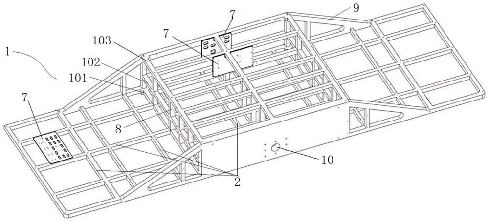
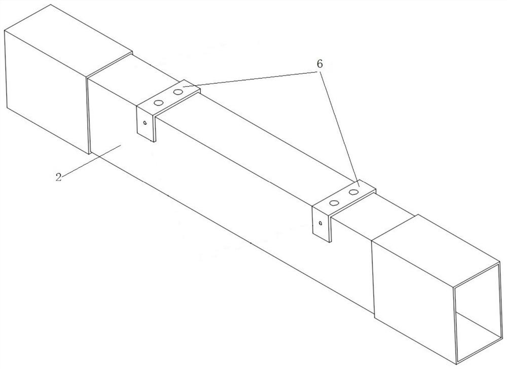
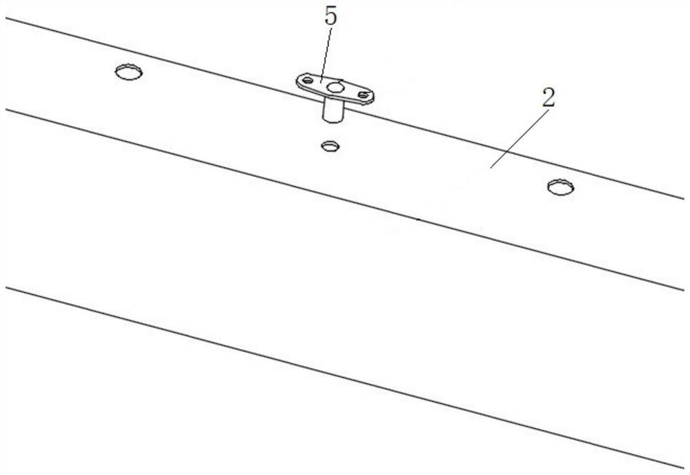
[0030] Such as figure 1 As shown, a carbon fiber antenna skeleton includes a multi-layer frame, a plurality of inner joints 3 and a plurality of outer joints, the multi-layer frame forms a three-dimensional hollow skeleton 1, and each layer of the frame is formed by splicing rectangular square tubes 2, The rectangular square tubes 2 inside each frame are connected by internal jo...


PUM


Abstract

A carbon fiber antenna skeleton disclosed by the present invention comprises a multi-layer frame, a plurality of internal connectors and a plurality of external connectors. The multi-layer frame forms a three-dimensional hollow skeleton, each layer of frame is formed by splicing rectangular square tubes, and the rectangular square tubes in each layer of frame are connected through the internal connectors. Each layer of frame is connected with the adjacent layer of frame through an external connector, the rectangular square tube is provided with a wire clamp embedded part used for installing an antenna cable and an equipment embedded part used for installing a radar assembly, and the frames, the internal connectors, the external connectors, the wire clamp embedded parts and the equipment embedded part are all made of carbon fiber materials. The carbon fiber antenna skeleton has the advantages that the weight of the antenna framework is reduced to the maximum extent, and more mounting points are provided, so that the light weight requirement and the mounting point position requirement of the existing antenna reflecting plate are met.

Description

technical field [0001] The invention relates to a carbon fiber antenna skeleton forming technology, and more particularly relates to a carbon fiber antenna skeleton. Background technique [0002] For airborne and spherical electronic equipment such as radar, due to the limited carrying capacity of the platform, the weight of the equipment load is a very important indicator. Antenna is one of the main components of radar equipment, and it occupies a large proportion in the weight distribution of the system. As for the new phased array antenna in the form of an array, a considerable part of the total weight of the antenna system is distributed on the reflector as the mounting surface and equipotential surface, so the lightweight design and manufacture of the reflector has obvious significance . How to make the antenna achieve maximum weight reduction on the basis of meeting the requirements of various indicators, using carbon fiber and other composite materials to make refle...

Claims


Application Information

Patent Timeline
Patent Type & Authority Applications(China)
IPC IPC(8): H01Q1/12H01Q15/14H01Q19/10G01S7/02
CPCH01Q1/12H01Q15/14H01Q19/10G01S7/02Y02A90/10
Inventor 韦生文李直赵玉申李磊孙艳龙薛伟锋
Owner CHINA ELECTRONIC TECH GRP CORP NO 38 RES INST
Why Eureka
Try Eureka