
Display filter and display apparatus having the same

A filter, wavelength technology that can be used in identification devices, optical/shielding devices, AC plasma display panels, etc., to solve problems such as limitations, deterioration of color reproducibility, deterioration of color purity, etc.

Inactive Publication Date: 2007-08-29
SAMSUNG CORNING CO LTD
View PDF3 Cites 9 Cited by
  • Summary
  • Abstract
  • Description
  • Claims
  • Application Information

AI Technical Summary

Problems solved by technology

Because color-correcting layers selectively absorb wavelengths corresponding to the range of about 580 nm to about 600 nm, they are limited in accurately representing colors as primary colors in the visible spectrum
Specifically, according to the color correction layer of the conventional technology, the color purity of red (R) is improved, however, there is a problem that the color purity of green (G) and blue (B) deteriorates
[0011] Therefore, when using a PDP filter containing a color correction layer, the color reproducibility of fully expressing the primary colors in the visible spectrum deteriorates

Method used

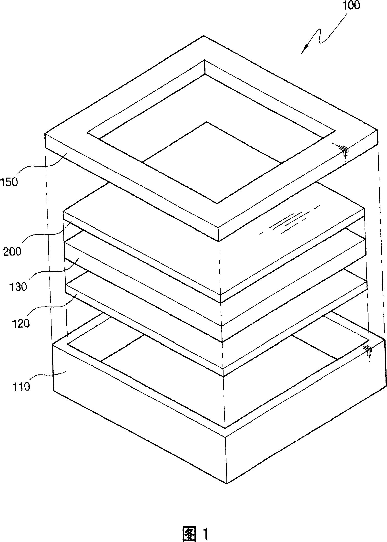
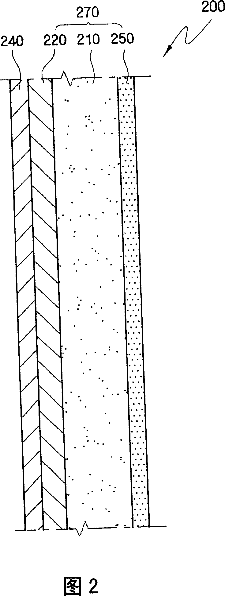
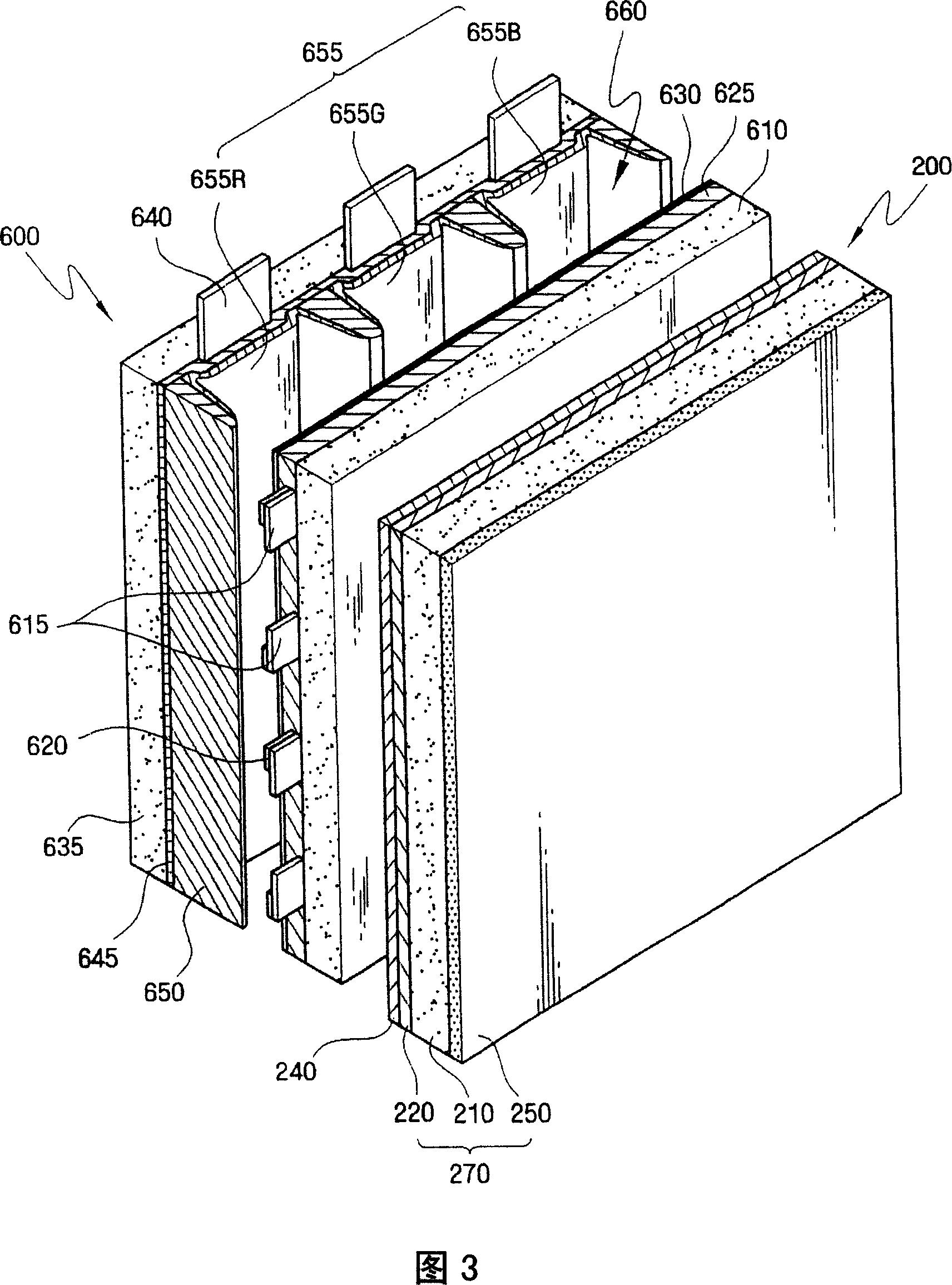

Image

  • Display filter and display apparatus having the same
  • Display filter and display apparatus having the same
  • Display filter and display apparatus having the same

Examples


experiment Embodiment 1

[0074] A PDP device including a PDP filter similar to the PDP filter described above with reference to FIG. 3 was prepared. Here, the PDP filter is formed by coating a color correction layer on the surface of the filter substrate after preparing a filter substrate having a multilayer structure of a transparent substrate, an electromagnetic wave shielding layer, and an antireflection layer. The transparent substrate is formed of semi-tempered glass, and the electromagnetic wave shielding layer is formed of a conductive mesh film formed on the surface of the transparent substrate. Also, an antireflection layer is formed on the other surface of the transparent substrate.

[0075]Here, the color correction layer is formed by the method described below. After mixing the color correction colorant with the solid PMMA polymer resin, the mixture of color correction colorant and solid PMMA polymer resin was stirred using MEK organic solvent for more than 1 hour. Here, a polymethine-ba...

comparative experiment Embodiment 1

[0078] A PDP filter-containing PDP device substantially similar to Experimental Example 1 was prepared except that no color correction colorant was included in the color correction layer. For Comparative Experimental Example 1, only a polymethine-based colorant having a maximum absorption wavelength corresponding to about 590 nm was used as a color correction colorant.

[0079] When the PDP filter is used, the transmittance corresponding to the wavelength change is measured, and the curve of FIG. 4C can be obtained. Here, FIG. 4C shows a graph of the transmittance of the PDP filter prepared by Comparative Experimental Example 1 with respect to wavelength.

comparative experiment Embodiment 2

[0081] A PDP device without a PDP filter is prepared.

[0082] Similar to Table 1 below, using the PDP filters obtained in Experimental Example 1, Comparative Experimental Examples 1 and 2, CIE chromaticity was measured. Also, the NTSC standard is recognized as a standard for CIE chromaticity.

[0083] [Table 1]

[0084] R

CIE(x,y)

G

CIE(x,y)

B

CIE(x,y)

color again

current area

NTSC standard

(0.670,0.330)

(0.210,0.710)

(0.140,0.080)

0.1582

Experimental example 1

(0.670,0.3 19)

(0.236,0.713)

(0.151,0.059)

0.1587

Comparative Experiment Example 1

(0.655,0.335)

(0.251,0.687)

(0.150,0.071)

0.1424

Comparative Experiment Example 2

(0.646,0.343)

(0.261,0.679)

(0.150,0.068)

0.1363

[0085] As shown in Table 1, the PDP device of Experimental Example 1 can obtain a color reproduction area greater than the NTSC standard, and compared with the PDP...


PUM


Abstract

A display filter (200) and a display apparatus including the display filter, which can enhance color purity of light sources of a red color, a green color, and a blue color (RGB), thereby improving color reproducibility are provided. The display filter includes: a filter base (270); and a color correction layer (240) which is formed on a surface of the filter base, and selectively absorbs a wavelength corresponding to about 490 nm to about 510 nm, and about 540 nm to about 600 nm. Here, a color reproduction area of a Commission Internationale de l'Eclairage (CIE) chromaticity coordinate increases to be greater than about 0.01 by the filter base and the color correction layer.

Description

[0001] Cross References to Related Applications [0002] This application claims priority from Korean Patent Application No. 10-2006-0017351 filed in the Korean Intellectual Property Office on February 22, 2006, and the disclosure of this application is hereby incorporated by reference. technical field [0003] The present invention relates to a display filter and a display device including the display filter, more particularly, to a display filter capable of improving the color purity of red, green and blue (RGB) light sources, thereby improving color reproducibility, and A display device including the display filter. Background technique [0004] As modern society becomes more information-oriented, technologies of elements and devices related to image display are also remarkably advancing, and these elements and devices are becoming widespread. Display devices employing parts and devices related to optoelectronic technology are becoming popular and used to a large extent ...

Claims


Application Information

Patent Timeline
Patent Type & Authority Applications(China)
IPC IPC(8): H01J17/02H01J17/16G02B5/20H05K9/00G02B5/22G09F9/00
CPCH01J11/10H01J2211/444H01J11/44G02B5/20
Inventor 赵偗任文胜瑚赵隐永安德基
Owner SAMSUNG CORNING CO LTD
Learn More