Laser modulator digital automatic bias voltage control device

A laser modulator and automatic bias technology, applied in the field of communication transmission, can solve the problems of uncontrollable jump position of control voltage, large influence of filter discreteness, large change of phase delay, etc., and achieve good passband performance and phase The effect of small delay and increased locking speed

Inactive Publication Date: 2007-08-29
HUAWEI TECH CO LTD
View PDF0 Cites 23 Cited by
  • Summary
  • Abstract
  • Description
  • Claims
  • Application Information

AI Technical Summary

Problems solved by technology

[0010] The invention provides a digital automatic bias voltage control device for a laser modulator, which is used to solve the problems in the prior art that the filter is greatly affected by the discreteness of the device, the phase delay changes greatly under the condition of temperature change, and it cannot be realized The problem of poor controllability and adjustability caused by the locking of the peak point of the PD electrical signal (that is, the maximum amplitude of the PD electrical signal), the uncontrollable jump position of the control voltage, and the lack of a control communication interface

Method used


Image

  • Laser modulator digital automatic bias voltage control device
  • Laser modulator digital automatic bias voltage control device
  • Laser modulator digital automatic bias voltage control device

Examples


Embodiment Construction

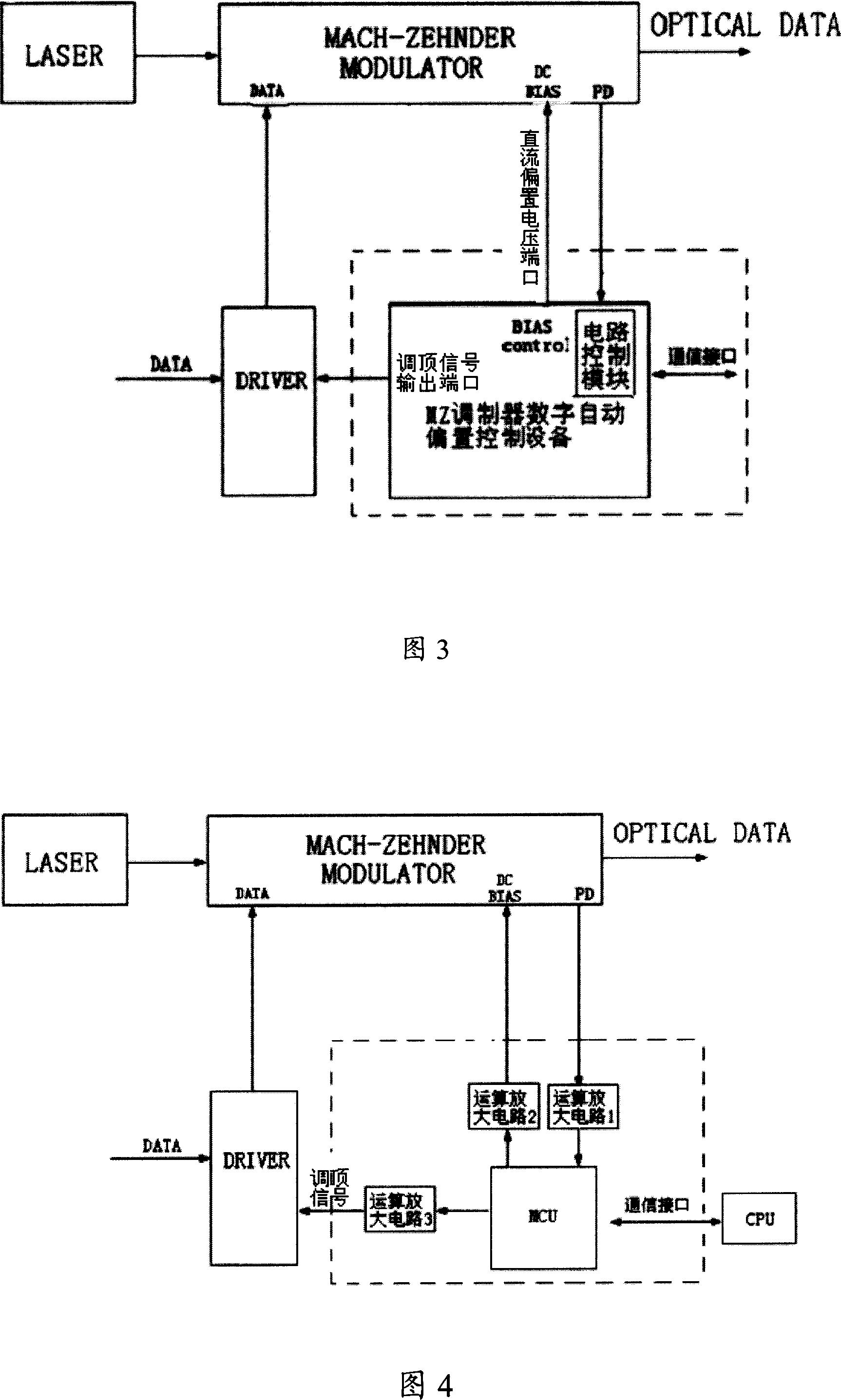
[0035]Fig. 3 is a functional schematic diagram of the MZ modulator digital automatic bias control device of the present invention. The MZ modulator digital automatic bias control device in the present invention mainly includes a circuit control module, and a top-adjustment signal output port connected to the circuit control module for outputting a top-adjustment signal, and a DC output port for outputting a DC bias voltage. A bias voltage output port, a PD electrical signal input port for inputting PD electrical signals, and a communication interface for communicating with other devices. A signal PD electrical signal generated by the optocoupler in the laser modulator that can reflect the characteristics of the modulated output optical signal of the laser modulator is input to the circuit control module through the PD electrical signal input port, and the circuit control module is used to control the top adjustment signal and The operation of the DC bias voltage makes it consi...


PUM


Abstract

The control device is applied to laser modulator installed on light laser. The control device includes following parts: an output port for adjusted peak signal, and the outputted peak signal is coupled to laser modulator after driven and modulated by the modulator; a output port of a DC bias voltage, and the outputted DC bias voltage is coupled to laser modulator; an input port for PD electrical signal output from the laser modulator; a control module in use for controlling operations of drive of modulator and the DC bias voltage, and making consistent between function curves of photovoltaic conversion in laser modulator. Comparing with prior art, the invention solves issues of large influence on filter caused by discretion of parts, large variety of phase delay when temperature changes, unable to lock peak point of PD electrical signal, and not good controllable adjustability caused by not controllable jumping position of bias control voltage, and no control communication port.

Description

technical field [0001] The invention relates to the field of communication transmission, in particular to a digital automatic bias voltage control device suitable for an optical signal transmission system requiring high performance and long-term stability. Background technique [0002] BIAS (bias control bias control) level control has been widely used in high-speed external modulation WDM transmitter modules, and the control uses the application method of integral or half-power point bias control regulator. The main principle of control is to use the regulator's working nonlinear principle to generate an error signal, and extract its amplitude and directional phase deviation from the signal. This erroneous signal is completely fed back to the bias control port of the regulator for feedback control, so as to achieve high performance and long-term stability of the optical signal transmission system. [0003] Using amplitude modulation (AM) digital RF (Radio Frequency) drive ...

Claims


Application Information

Patent Timeline
Patent Type & Authority Applications(China)
IPC IPC(8): H04B10/155H01S5/042H04B10/508
Inventor 张展袁胜田丁
Owner HUAWEI TECH CO LTD
Why Eureka
Try Eureka