Frequency measuring system for universal voltage input power frequency signal

A frequency measurement and power frequency signal technology, applied in the field of electrical systems, can solve the problems of difficult to guarantee accuracy, long input signal delay, large size of the frequency measurement system, etc., and achieve the effect of poor hardware versatility and good circuit anti-interference ability.

Inactive Publication Date: 2014-04-02
BEIJING SIFANG JIBAO AUTOMATION
View PDF6 Cites 16 Cited by
  • Summary
  • Abstract
  • Description
  • Claims
  • Application Information

AI Technical Summary

Problems solved by technology

[0004] The purpose of the present invention is to overcome the problems of large volume, complex circuit, long delay for input signal, difficult to guarantee accuracy or narrow application range in the power system frequency measurement system in the prior art, and propose a universal voltage input system. Power Frequency Signal Frequency Measurement System

Method used


Image

  • Frequency measuring system for universal voltage input power frequency signal
  • Frequency measuring system for universal voltage input power frequency signal
  • Frequency measuring system for universal voltage input power frequency signal

Examples


Embodiment Construction

[0022] The technical solution of the present invention will be further introduced in detail below in conjunction with the accompanying drawings of the description.

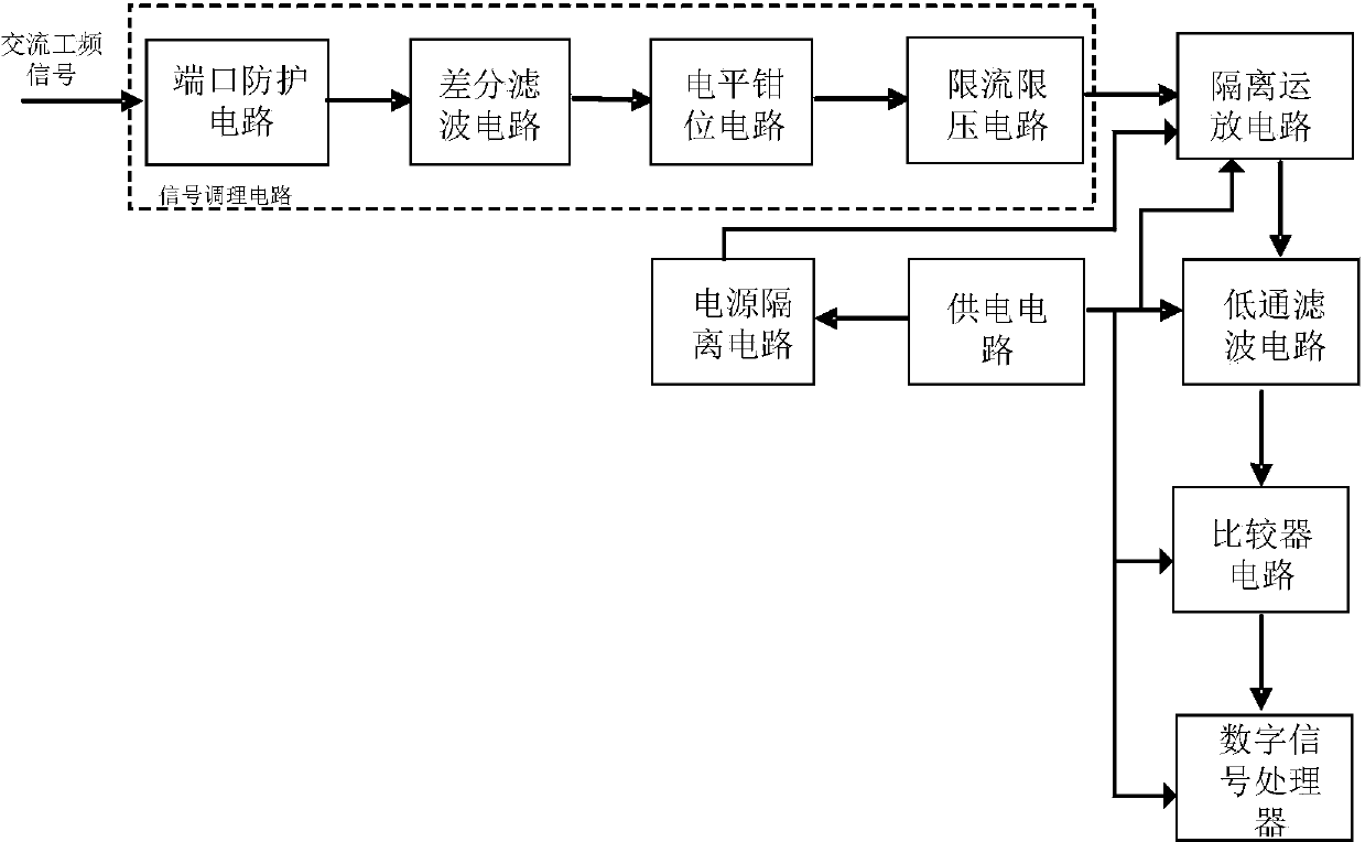
[0023] The invention provides a method for measuring the frequency of a power frequency signal with a universal voltage input, such as figure 1 Shown is a schematic diagram of a power frequency signal frequency measurement circuit with a universal voltage input. This method converts the wide-range universal voltage input signal transmitted by the power secondary transformer into a fixed-frequency pulse signal through a signal conditioning circuit, an isolated operational amplifier circuit, a low-pass filter circuit and a comparator circuit (ie, a differential comparator circuit). , sent to the digital signal processor for real-time operation and acquisition. The signal conditioning circuit is sequentially connected with the port protection circuit, the differential filter circuit, the level clamping circuit and t...


PUM


Abstract

The invention discloses a frequency measuring system for a universal voltage input power frequency signal. The system consists of a signal conditioning circuit, an isolation operational amplification circuit, a lowpass filtering circuit, a comparator circuit and a digital signal processor, wherein the signal conditioning circuit is designed by adopting a universal circuit, an alternating current power frequency signal is suitable for a voltage range from 1V to 250V, thus meeting most application occasions of a power system, the isolation operational amplification circuit is used for isolating strong current signals from weak current signals and replacing the traditional transformer components, the lowpass filtering circuit and the comparator circuit are matched with the isolation operational amplification circuit for changing alternating current signals into direct current signals, and signals output by the comparator circuit do not need to be subjected to signal isolation and can be directly connected to the digital signal processor for finishing frequency calculation. The method has the characteristics of simple circuit, small size, little phase delay and the like.

Description

technical field [0001] The application belongs to the technical field of electrical systems, and in particular relates to the frequency measurement technology of relay protection devices. Background technique [0002] In the traditional power system relay protection device, the input signal is the power frequency (50Hz) signal transmitted by the secondary transformer, the voltage value may be tens of volts to hundreds of volts, and the relay protection device needs a cycle (20mS) Collect real-time data with a fixed number of points (24 points or 40 points), and based on these data, the relay protection device must perform real-time protection algorithm calculations to determine whether there are various faults such as short circuit or grounding in the power grid. In order to ensure the accuracy and reliability of the protection algorithm, the data collected by the cycle wave should be an integral multiple of the actual frequency (50Hz), and the phase delay should be as small...

Claims


Application Information

Patent Timeline
Patent Type & Authority Applications(China)
IPC IPC(8): G01R23/02
Inventor 徐万方陈建英徐刚唐喜
Owner BEIJING SIFANG JIBAO AUTOMATION
Why Eureka
Try Eureka